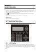
Section 8 System Operation Operation of the control panel is simple. Menus guide you step-by-step through operations. This section of the manual is an overview of the operation menus. Please read this entire section carefully before operating the panel. Press to view Main Menu: Select the desired menu option. Enter your access code if prompted. Note: See Section 7.8 for information on how to modify user access code profiles. Default Codes: User Code (factory-programmed as 1111).
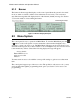
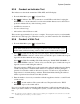
Model 5700 Installation and Operation Manual 8.1.2 Banner The banner is the message that displays on the control panel when the system is in normal mode (no alarm or trouble condition exists and menus are not in use). You can create a customized message that will display instead of the internal (default) message. See Section 7.5.9 for information on customizing the banner. Figure 8-2 Banner Display Examples 8.2 Menu System The control panel is easy to operate from Main Menu.
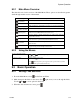
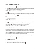
System Operation 8.2.1 Main Menu Overview The chart below is a brief overview of the Main Menu. These options are described in greater detail throughout this section of the manual. Main Menu Options 8.2.2 Description From here both menus can access Fire Drill and Indicator Test. 1 System Tests 2 Point Functions 3 Event History 4 Set Time and Date Set time and date for the system. 5 Printer Options Options for controlling a printer if attached to the system.
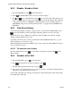
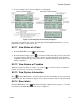
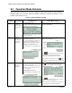
Model 5700 Installation and Operation Manual 8.3.2 Disable / Enable a Point 1. From the Main Menu, select 2. Select 1 2 for Point Functions. for Disable/Enable Point. A list of modules displays. 3. Use and to move through the list. Press to select the module where the point you want to disable/enable is located. A description of the point should display. The fourth line of the screen should show "NORMAL" (meaning that the point is currently enabled) or "DISABLED" (the point is currently disabled).
System Operation 8.3.5 Conduct an Indicator Test The indicator test checks the annunciator LEDs, PZT, and LCD display. 1. From the Main Menu, press 1 for System Tests. 2. Press 2 for Indicator Test. The system turns on each LED several times, beeping the PZT as it does so. At the same time it scrolls each available character across the LCD. A problem is indicated if any of the following occurs: • An LED does not turn on; • You do not hear a beep; • All four lines of the LCD are not full.
Model 5700 Installation and Operation Manual 8.3.7 Conduct a Dialer Test 1. From the Main Menu, press 1 for System Tests. 2. Select 5 for Dialer Test. The screen will display “Manual dialer test started”. When the test is completed, you will be returned to the . 8.3.8 Silence alarms or troubles Press and enter your code or rotate the key at the prompt. If an external silence switch has been installed, activating the switch will silence alarms or troubles.
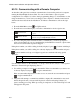
System Operation 5. A screen similar to those shown in Figure 8-3 will display. Figure 8-3 Checking Detector Sensitivity Compliance If a printer is attached to the system (via a Module 5824 Serial/Parallel Interface), you can print detector status (see Section 8.3.16). 8.3.11 View Status of a Point 1. From the Main Menu, select 2 for Point Status. 2. From the list that displays, press to select the module where this point is located.
Model 5700 Installation and Operation Manual 8.3.15 Communicating with a Remote Computer An installer at the panel site can initiate communications between the panel and a computer running the Silent Knight Software Suite. You can use this feature to upload a panel configuration. For example, if you have made programming changes to an installation on site using an annunciator, you can send your changes to the computer, so that the central station will have the latest data about the installation.
System Operation 8.3.16 Working with a Printer If you are using the Model 5824 Serial/Parallel Interface, several printing options are available. See Section 4.6 for information about installing the 5824. 1. From the Main Menu, select 5 Printer Options. 2. From the next screen, select the 5824 module where the printer is connected. 3. If the printer is not currently busy printing another report, a screen with the following options will be available. If the printer is busy, a message will display.
Model 5700 Installation and Operation Manual 8.4 Operation Mode Behavior The control panel can be in one of seven conditions at any given moment: Normal, Alarm, Prealarm, Supervisory, Trouble, Silenced, and Reset. Table 8-2 describes the behavior of the panel in each of these modes. Table 8-2: Operation Modes of FACP Operation Mode Normal Occurs When System Behavior In This Mode You Can Enter the appropriate code, or rotate the key to SYSTEM POWER LED is on.
System Operation Table 8-2: Operation Modes of FACP Operation Mode Trouble Occurs When System Behavior A system trouble The dialer seizes control of the phone line and calls the central station. condition occurs. The on-board annunciator sounds a loud, pulsing beep in the sequence one second on, nine seconds off. In This Mode You Can Press (down arrow) to view the trouble. A screen similar to this one displays. SYSTEM TROUBLE LED flashes. The LCD displays a screen similar to this one.
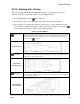
Model 5700 Installation and Operation Manual 8.5 Releasing Operations This control panel supports two types of releasing, Double Interlock Zone, and Single Interlock Zone. The Double Interlock Zone operation requires an interlock switch input in the system, and the Single Interlock does not. An interlock switch is typically a dry-contact pressure switch. Important! These releasing functions can only be done if the system has a 5496 intelligent power module included.
System Operation 8.5.1 Single Interlock Zone Releasing A single interlock zone utilizes a minimum of two addressable detectors, and a designated manual release switch. Important! Only addressable detectors can be used. No conventional detectors can be used. Each Single Interlock Zone input requires at least one manual release switch. Conditions Required for an Pre-Alert Output Activation If any single addressable detector is activated, the "Pre-Alert" output will activate.
Model 5700 Installation and Operation Manual 8.5.2 Double Interlock Zone Releasing A Double Interlock Zone uses a minimum of two Addressable detectors, a designated manual release switch, and an interlock switch input. An interlock switch is typically a dry-contact pressure switch and will be referred to as an interlock/pressure switch in this document. Important! Only addressable detectors can be used. No conventional detectors can be used.