
User Manual

Model 5820XL / 5820XL-EVS Installation Manual LS10061-001SK-E
8-15
8.7 Releasing Operations
The control panel supports two types of releasing, Double Interlock Zone, and Single Interlock Zone. The
Double Interlock Zone operation requires an interlock switch input in the system, and the Single Interlock zone
does not. An interlock switch is typically a dry-contact pressure switch.
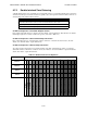
When Single or Double Interlock Zone releasing is selected, the system will automatically default the following
system parameters:
Note: The defaults created can be modified through programming if desired.
• Output Group 2 is created. Output Group 2 will be defaulted as an "Alarm" output group for all releasing
zones. NAC [34:001] is assigned to Output Group 2.
• Output Group 3 is created. Output Group 3 will be defaulted as an “Pre-Alarm” output group for all
releasing zones. NAC [34:002] is assigned to Output Group 3.
• Output Group 4 is created. Output Group 4 will be defaulted as a "Release" output group for all releasing
zones. NAC circuit [34:003] is assigned to Output Group 4.
Note: The installer must define which input points will be used for detectors, manual release switches, or inter-
lock/pressure switches.
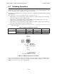
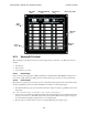
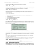
Figure 8-5 Wiring Configuration for Solenoid
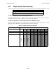
Do not mix cross alarming zones with smoke verification zones. There must be at least two automatic detection
devices in each protected space. Spacing must be reduced to 0.7 times the linear spacing in accordance with
NFPA 72. See Section 7.3 for zone option programming.
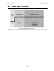
Table 8-2: Approved Releasing Solenoids
Manufacturer Part Number Rating Current Freq
Asco T8210A107 24 VDC 3A max 0 Hz
8210G207 24 VDC 3A max 0 Hz
Model 7641*
Must Mounted
at the Solenoid
*Order as P/N 7641B