
User Manual

LS10061-001SK-E Emergency Voice System Operation
9-20
9.12 Defining Output Group Type
Each output group is defined as either a voice output group or a non-voice output group. Output points that are
audio circuits (all circuits on the EVS-50W, EVS-125W, EVS-100W, EVS-INT50W and EVS-CE4) can only be
assigned to voice output groups. Output points that are non-voice circuits (all other points and circuits that are on
all modules except the EVS-50W, EVS-125W, EVS-100W, EVS-INT50W and EVS-CE4) are assigned to non-
voice output groups.
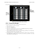
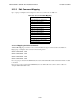
Each of the output groups defined as voice can be mapped to a particular switch and LED on the EVS-
VCM,EVS-RVM and EVS-SW24. This allows the user to see the state of the voice groups assigned to the
switches. This also lets the user individually select which areas they want to do a live page into.
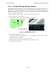
Output groups not defined as voice groups can also be assigned to these switches as long as there is a voice group
already assigned to the group. This allows for dynamically activating/deactivating both voice and strobes/other
outputs in an area with a single button press. See section 9.2.3.2.
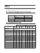
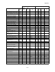
Figure 9-11 Corresponding Switch and LED for Mapping Output Groups
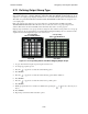
1. To get to this menu item repeat steps 1 through 6 of Section 7.4.1.
2. To edit group properties, press 2.
3. Press the or arrows to select the desired latching option.
4. Press ENTER.
5. Press the or arrows to select the desired silencing option. Refer to Table 7-2.
6. Press ENTER.
7. Press the or arrows to select the desired reverse polarity option
8. Press ENTER.
9. Enable group activation for a condition (see Table 7-4) by pressing the or arrows to select Y (yes) or
N (no).
10. Press ENTER.
11. Repeat steps 9 and 10 for all the activation options.
EVS-VCM
EVS-SW24
Corresponding
Switch and LED Numbers
Corresponding
Switch and LED Numbers