
User Manual


LS10061-001SK-E Control Panel Installation
4-34
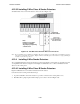
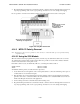
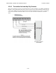
5. If necessary, adjust loop current using the potentiometer (R10) on the 5220 board. Normal loop current is 2-
to-8 mA with a 1k ohm remote station receiving unit. Maximum loop resistance is 3k ohm.
Figure 4-42 Polarity Reversal Connection Using the 5220 Module
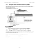
4.14.3.2 Using the 7644-L8* Module
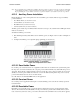
When the 7644 is used for polarity reversal, it allows alarm and trouble events to be reported to a remote site.
Alarms will override trouble conditions and it will not be possible to reset the remote indicator until the condition
is cleared and the control panel is reset.
To install the 7644-L8 for polarity reversal:
1. Wire the 7644-L8 to the control panel as shown in Figure 4-43. Do not install an EOL resistor on the termi-
nals of the Flexput circuit used.
Note: Use only Flexput circuits on the control panel for reverse polarity.
2. Program the Flexput circuit as a notification circuit. See Section 7.5.2.
3. Map the group to activate constant on from the zone event. See Section 7.3.1.3.
4. Program the output group characteristics as non-silenceable and reverse polarity. See Section 7.4.1.2.
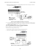
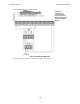
Figure 4-43 Polarity Reversal Connection Using the 7644-L8
Note: *When ordering, request as P/N 7644-L8
All circuits power-limited.
All wiring supervised.
Note:
Flexput circuit 1 and Relay 1
used as examples. Any
Flexput circuit and either
relay 1 or relay 2 could
be used.
Jumper these terminals
when City Box is not used.
Intended for connection to a Polarity Reversal
circuit of a Remote Station receiving unit having
compatible ratings.