
User's Manual


Installing the Serial Device Server Silex Page 7
Part Number 140-00188-180
• If the Serial Device Server is operating properly, the LEDs will blink momentarily and then go out,
the yellow and green LEDs will illuminate if the wireless network is active, and the orange LED
will illuminate, indicating the device is receiving power.
• The unit powers up in the Normal mode, which provides for connection from the network to
device(s) connected to the serial port of the Serial Device Server.
• If the orange LED blinks continuously in a regular pattern, a problem exists. If this is the case, try
powering the unit OFF and then ON again.
.
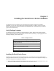
6. Connect the Serial Device Server to your network through a switch or hub using a category 5 (CAT5)
Ethernet cable. Serial Device Server wireless models automatically detect the presence of this cable,
and will switch off the wireless networking functionality as long as the cable is plugged in.
7. The Serial Device Server’s IP address must be configured before a network connection is available.
If your network offers DHCP (Dynamic Host Configuration Protocol), the Serial Device Server will
automatically search for a DCHP server upon power up and obtain an IP address. If your network
does not offer DHCP, a static (fixed) IP address must be assigned (see your system administrator for
assistance). If you use DHCP, make sure that the length of the DHCP lease is adequate so that the
IP address of the Serial Device Server does not change.
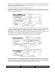
Monitoring Serial Device Server Status
You can monitor the Serial Device Server status using the yellow, green and orange LED status
indicators on the monitor. Table 2 defines the default functions of the LED status indicators.
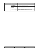
Table 2 Status Monitors
Function State Status
On The Serial Device Server is receiving power
Off The Serial Device Server is not receiving power
Power
Orange
Blinking The Serial Device Server power supply is malfunctioning
Yellow Off
Green Off
No network activity
Yellow On
Green Off
10base-T network active
Yellow Blinking
Green Off
10base-T network data received
Network Status
Yellow or Green
Yellow Off
Green On
100base-TX network active
NOTE: Pin 9 is normally configured for supplying +5V from an external power source in lieu of using the AC power
supply adapter. If you wish to use this pin as the Ring Indicator (RI) modem signal on the SX-500 (not available on the
SX-510), open the enclosure and move the jumper on connector JP1 onto pins 2 and 3 of this connector.
NOTE: SILEX RECOMMENDS USING A HARDWIRED ETHERNET CONNECTION FOR CONFIGURING WIRELESS SERIAL
DEVICE SERVERS. If you have a wireless Serial Device Server model and cannot use an Ethernet connection, refer to
step 4 in the First Time IP Address Configuration section of this chapter for instructions on how to set up the Serial
Device Server using a completely wireless Ad Hoc environment.