Serial Server Ethernet and Wireless Serial Servers Product Photo Installation and User’s Guide Part Number 40179-120 Revision X5
Notice TROY GROUP, INC. SPECIFICALLY DISCLAIMS THE IMPLIED WARRANTIES OF MERCHANTABILITY AND FITNESS OF THIS PRODUCT FOR A PARTICULAR PURPOSE. TROY shall not be liable for any errors contained in this manual or for any damages resulting from loss of use, data, profits, or any incidental or consequential damages arising from the use of TROY products or services. The information contained in this documentation is subject to change without notice.
Serial Server User’s Guide TABLE OF CONTENTS Section 1 – Product Overview Introduction............................................................................................................................ 1-1 Package Contents ................................................................................................................... 1-1 About this User’s Guide.........................................................................................................
Serial Server User’s Guide Appendix A – Safety and Regulatory Notices Information for United States Users ..................................................................................... A-1 Declaration of Conformity (FCC)......................................................................................... A-2 Information for Canadian Users (IC notice) ......................................................................... A-2 Information for European Users .......................................
Serial Server User’s Guide Section 1: Product Overview Introduction The TROY Serial Server is a high-performance, standalone device designed to connect a wide range of serial devices (i.e., security devices, telecommunications equipment, modems, data display devices, industrial instrumentation, etc.) to an Ethernet network.
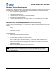
Serial Server User’s Guide Windows™ System Requirements To configure the settings of the TROY Serial Server (wired and wireless versions) using the provided ExtendView Utility in Windows, your Windows-based system should include the following components: A PC with a 133 MHz or higher processor Microsoft Windows 98SE, ME, 2000, XP, or 2003 server operating system At least 64 MB of RAM (memory) At least 10 MB of free hard disk space (to install the software) A CD-ROM drive (to load the software) An Internet c
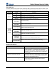
Serial Server User’s Guide Component Descriptions The Serial Server includes the following components as described below: Power connector – The power supply cable plugs into this connector. Test button – Pressing this button for less than five seconds will print a test page (if the device is connected to a serial printer). Pressing and holding this button for more than five seconds will reset the serial server to factory default settings.
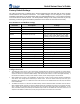
Serial Server User’s Guide LED Indicators The TROY Serial Server provides three multifunction LED (Light Emitting Diode) indicators (yellow, green, and orange) for easy monitoring. The following table defines the function of each LED.
Serial Server User’s Guide Factory Default Settings The TROY Serial Server is shipped with a default configuration that will work with the most common serial-to-Ethernet and wireless connections. The default settings can be changed to suit specific installation requirements via the ExtendView Utility, the embedded Web server, or via a Telnet connection to the serial server’s internal console.
Serial Server User’s Guide Section 2: Hardware Installation Install the TROY Serial Server (for wired and wireless models) Follow the steps below to install the TROY Serial Sever. In most cases, the Serial Server’s factory default settings should be sufficient for most serial connections; however, some of the configuration settings may have to be changed for your particular installation.
Serial Server User’s Guide Section 3: Configuration and Management Configuration Options After the hardware installation has been successfully completed, the Serial Server can be configured and managed via an Ethernet and/or wireless connection using the TROY ExtendView Utility (recommended), the embedded web (HTTP) server pages, or the Serial Server’s internal configuration console, which can be accessed via a Telnet connection or directly through the Serial Server’s serial port.
Serial Server User’s Guide Command Console a command-line-oriented console. contains some advanced features not available through ExtendView or the Web Browser Interface. the default password is ACCESS. can be accessed via TELNET or via a direct connection to the Serial Server’s serial port. type HELP for a list of console commands.
Serial Server User’s Guide USING THE WEB BROWSER INTERFACE TO CONFIGURE THE SERIAL SERVER (NON-WINDOWS SYSTEMS): To configure the Serial Server using non-Windows operating systems (e.g., Unix systems), a standard web browser (e.g., Internet Explorer or Netscape Navigator) can be used to access the Serial Server’s embedded Web (HTTP) server pages, which contain the Serial Server’s configuration options. No additional software is required. 1. Ensure your PC is connected and has access to your network. 2.
Serial Server User’s Guide USING THE INTERNAL CONFIGURATION CONSOLE TO CONFIGURE THE SERIAL SERVER: 1. Ensure the serial sever is connected via an Ethernet cable to the host computer. 2. From the Windows Start menu, click on Run, and then type the following command (where x.x.x.x. is the IP address of the Serial Server). The system will use the default port 23. telnet X.X.X.X 3.
Serial Server User’s Guide First-Time Configuration of the Wireless Serial Server Using 802.11b (wireless models only) Although the Serial Server can be configured using a wireless connection, it is recommended that the Serial Server be initially configured using a wired connection as described on the previous pages. The Serial Server’s wireless network interface supports all modes of 802.11b at 1, 2, 5.5, and 11 Mbps.
Serial Server User’s Guide Verifying the Serial Server’s Connection to a Serial Device 1. Verify that both the Serial Server and the connected serial device are powered on and ready, and that a serial cable is properly connected between the Serial Server and serial device (i.e., transmit signal output from the Serial Server going to the receive signal input on the serial device, ground leads connected together, etc.).
Serial Server User’s Guide Changing the Serial Settings In order to establish communication between the Serial Server and a serial device, the serial settings for both devices must match. The serial settings can be changed using ExtendView (recommended), the web browser interface, or the Serial Server’s internal configuration console (refer to the previous sections for the installation and use of these utilities). Refer to page 1-5 for a list of factory default settings.
Serial Server User’s Guide Using the Modbus Protocol Modbus is a widely used industrial device communications protocol that provides “client/server” communications between devices connected on different types of buses or networks. The TROY Serial Server supports the Modbus serial line version of the protocol used for communicating with many types of industrial devices (e.g., instruments, meters, controllers, switches, etc.) over a serial-to-Ethernet connection.
Serial Server User’s Guide Section 4: Troubleshooting Introduction This section describes procedures for troubleshooting problems you may encounter with the TROY serial server, and is divided into the following sections: Installation Problems Intermittent Problems Protocol-Specific Problems Troubleshooting Installation Problems If you cannot access the connected serial device via the Serial Server, first check the network connection and cabling.
Serial Server User’s Guide Troubleshooting Windows Problems If you are having trouble accessing the connected serial device through Windows, ensure you can ping the TROY Serial Server using the DOS command PING ipaddress, where ipaddress is the IP address of the TROY Serial Server. If you cannot ping the serial server, you will not be able to access the serial device.
Serial Server User’s Guide Section 5: Where to Get Help Obtaining Technical Assistance TROY technical support is available to assist you with any questions concerning the setup, operation, or maintenance of your TROY200 Series Print Server. Worldwide Web Support Located at http://www.troygroup.com/wireless, the TROY web site provides answers to many common technical questions and also includes copies of product manuals and literature, as well as utilities and firmware load images.
Serial Server User’s Guide Returning Products If you need to return a TROY product for any reason (failures, incorrect shipments, etc.), follow the steps below: 1. Contact the TROY Technical Support group at (304) 232-0899 to request a Return Goods Authorization (RGA) number (for North and South American customers), or call +49-7032-9454-21 (for European customers) and request a Return Material Authorization (RMA) number. 2. Be prepared with the serial number of the unit you are returning.
Serial Server User’s Guide Appendix A: Safety and Regulatory Notices Information for United States Users This equipment has been tested and found to comply within the limits for a Class B digital device pursuant to Part 15 of the FCC Rules. These limits are designed to provide reasonable protection against harmful interference in a residential installation.
Serial Server User’s Guide Declaration of Conformity (FCC) According to 47CFR, Part 2 and 15 for Class B Personal Computers and Peripherals; and/or CPU Boards and Power Supplies used with Class B Personal Computers: We: Located at: TROY GROUP, INC. 2331 South Pullman Street Santa Ana, CA USA Declare under sole responsibility that the product identified herein, complies with 47CFR Part 2 and 15 of the FCC rules as a Class B digital device FOR HOME OR OFFICE USE.
Serial Server User’s Guide Information for European Users The Serial Server and its built-in 802.11b wireless technology is in compliance with the Class B Information Technology Equipment requirements and other relevant provisions of European Directive 1999/5/EC. The limits for Class B equipment were derived for typical residential environments to provide reasonable protection against interference with licensed communications devices. The internal function is a radio device using the 2.
Serial Server User’s Guide Appendix B: Product Specifications COMPONENT SPECIFICATION Model TROY Serial Server Processor Motorola Coldfire MC5272 Flash Memory 2 Mbytes RAM Memory 8 Mbytes (SDRAM) Processor Speed 66 MHz Interfaces Supported Serial: RS-232, RS-422, RS-485 (via 9-pin jack) (ModBus support for RS-232 / RS-485 networks) Ethernet: 10/100Base-T (via RJ-45 8-wire jack) Baud Rates Supported (Kbps) 1200, 2400, 4800, 9600, 19200, 38400, 57600, 115200, 230400, 460800 Network Protocols
Serial Server User’s Guide Appendix C: Serial Port Pinouts PIN RS-232 (DTE) 1 DCD (Data Carrier Detect) Input 2 RxD (Receive Data) Input 3 TxD (Transmit Data) Output 4 DTR (Data Terminal Ready) Output 5 GND (Signal Ground) 6 DSR (Data Set Ready) Input 7 RTS (Request To Send) Output 8 CTS (Clear To Send) Input 9 RI (Ring) or +5 VDC power input (selectable via 3-pin jumper) PIN RS-422 and RS-485 (4-wire, full duplex) 2 RD+ (Receive Data +) Differential Input 3 TD+ (Transmit Data +) D
Serial Server User’s Guide Appendix D: Alternate Power Source Configuration The TROY Serial Server can be configured to use a +5 VDC input via Pin 9 on the DB-9 connector to power the unit instead of using the supplied power supply module. To configure the serial server to accept power via Pin 9, the serial server case must be opened, and the shunt at JP3 must be moved from Pins 2 and 3 to Pins 1 and 2 (towards the +5 indicator). The voltage measured at Pins 9 and 5 must be at least +4.
Serial Server User’s Guide RS-485 Half-Duplex Port In RS-485 half-duplex mode, the DB-9 male connector is configured as shown below. It is important to construct the cable so that an unshielded twisted pair (UTP) wire is used for the transmit/receive pair to minimize EMI emissions and maximize immunity to outside sources (see Figure 3). If the TROY Serial Server is the last device in a chain, then a 120-ohm terminating resistor should be placed across Pins 3 and 4. The Pin 9 connection is optional.
Serial Server User’s Guide Appendix E: Loading New Firmware 1. Run the TROY Wireless Update utility for TCP/IP. The About Update for TCP/IP window will be displayed. Click on OK to continue. The Select Update File window will be displayed. 2. Select UpdateFiles (*.bin) file type, locate the Serial Server bin file, and then click on Open. A window will be displayed (see next page) showing the file(s) you have selected including the revision level and date code for each file. Document #40179-120 Rev.
Serial Server User’s Guide 3. Verify that the file(s) are correct, and click on OK. The utility will begin searching for qualified serial servers present on the network. 4. When the search process is complete, click on OK to continue. A list of found devices will be displayed. Document #40179-120 Rev.
Serial Server User’s Guide 5. Select the desired Serial Server to be upgraded, click on the green icon, or click on UPDATE Æ START. The firmware update process will begin automatically as soon as the Serial Server is ready. 6. When the Serial Server is ready, the firmware upgrade will begin. The IP address of the serial server as well as the file you are loading will be displayed. Document #40179-120 Rev.
Serial Server User’s Guide 7. The update log will be displayed when the update process is finished. Click on Close to continue. Document #40179-120 Rev.