
User Guide


ELECTRICAL SPECIFICATION SSD-CXXX(I)-3600 DATA SHEET
SILICONSYSTEMS PROPRIETARY
This document and the information contained within it is confidential and proprietary to SiliconSystems, Inc.
All unauthorized use and/or reproduction is prohibited.
3600C-04DSR PAGE 6FEBRUARY 2, 2009
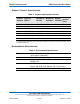
SIGNAL DESCRIPTIONS
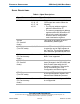
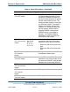
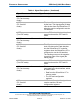
Table 8: Signal Descriptions
Signal Name Pin Type Description
A10-A0 8, 10, 11,
12, 14, 15,
16, 17, 18,
19, 20
I These address lines along with the
-REG signal are used to select the
following:
• The I/O port address registers
within the SiliconDrive CF
• The memory-mapped port address
registers within the SiliconDrive CF
• A byte in the card's information
structure and its configuration
control and status registers
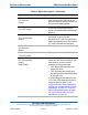
A10-A0
(PC Card I/O
mode)
This signal is the same as the PC
Card Memory Mode signal.
A2-A0
(True IDE mode)
18, 19, 20 I In true IDE mode, only A[2:0] are used
to select the one of eight registers in
the Task File. The remaining address
lines should be grounded by the host.
BVD1
(PC Card memory
mode)
46 I/O This signal is asserted high, because
BVD1 is not supported.
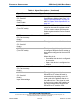
-STSCHG
(PC Card I/O
mode)
This signal is asserted low to alert the
host to changes in the RDY/-BSY and
Write Protect states while the I/O
interface is configured. This signal’s
use is controlled by the Card
Configuration and Status register.
-PDIAG
(True IDE mode)
In the true IDE mode, this input/output
is the Pass Diagnostic signal in the
Master/Slave handshake protocol.
BVD2
(PC Card memory
mode)
45 I/O This signal is asserted high, as BVD2
is not supported.