
User Guide


ELECTRICAL SPECIFICATION SSD-PXXX(I)-3100 DATA SHEET
SILICONSYSTEMS PROPRIETARY
This document and the information contained within it is confidential and proprietary to SiliconSystems, Inc.
All unauthorized use and/or reproduction is prohibited.
3100P-06DSR PAGE 13 FEBRUARY 2, 2009
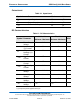
-REG
(PC Card memory
mode)
Attribute Memory
Select
44 I This signal is used during memory
cycles to distinguish between
common memory and register
(attribute) memory accesses. This
signal is set:
• High for common memory.
• Low for attribute memory.
-REG
(PC Card I/O
mode)
The signal must also be active (low)
during I/O cycles when the I/O
address is on the bus.
-DMACK
(True IDE mode)
In true IDE mode, this signal is used
by the host in response to DMARQ to
initiate DMA transfers. The DMARQ/
-DMACK handshake is used to
provide flow control during the
transfer. When -DMACK is asserted,
-CS0 and -CS1 are not asserted and
transfers are 16-bits wide.
-RESET
(PC Card memory
mode)
41 I When the pin is high, this signal
resets the SiliconDrive CF. The
SiliconDrive CF is reset only at power-
up if this pin is left high or open from
power-up. The SiliconDrive CF is also
reset when the Soft Reset bit in the
Card Configuration Option register is
set.
-RESET
(PC Card I/O
mode)
This signal is the same as the PC
Card Memory Mode signal.
-RESET
(True IDE mode)
In the true IDE mode, this input pin is
the active low hardware reset from the
host.
V
CC
(PC Card memory
mode)
13, 38 - +5V, +3.3V power.
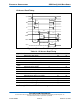
Table 8: Signal Descriptions (Continued)
Signal Name Pin Type Description