
User's Manual


Bluegiga Technologies Oy
Page 8 of 52
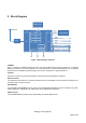
2 Block Diagram
32k EEPROM
PIO3
PIO4
26MHz XTAL
BPF
Antenna
PIO0
PIO1
PIO2
PIO5
SPI / PCM
USB
CSR8510
RF
RAM
ROM
MMU
MCU
I/O
LDO 3V3
LDO 1V8
3 x LDO
1V3
5V0 3V3 1V8
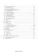
Figure 1: Block diagram of BT111
CSR8510
BT111 is based on CSR8510 dual mode chip. The chip includes all the functions required for a complete
Bluetooth radio with on chip LDO regulators. The chip provides SPI, PCM and USB interfaces. Up to 4 general
purpose I/Os are available for general usage, such as Wi-Fi coexistence or general indicators.
Antenna
Antenna is a ceramic monopole chip antenna. See the antenna characteristics in chapter 7.
Band Pass Filter
The band pass filter filters the out of band emissions from the transmitter to meet the specific regulations for
type approvals of various countries.
32k EEPROM
The embedded 32k EEPROM can be used to store customizable parameters, such as maximum TX power,
PCM configuration, USB product ID, USB vendor ID and USB product description.
26MHz Crystal
The embedded 26MHz crystal is used for generating the internal digital clocks.