
User's Manual


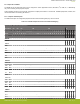


Table Of Contents
- 1. Key Features
- 2. Pinout
- 3. Interfaces
- 4. Module Software
- 5. Hardware Design Guidelines
- 6. Electrical Characteristics
- 7. RF Characteristics
- 8. Physical Dimensions and PCB Land Pattern
- 9. Soldering Recommendations
- 10. Tape and Reel Packaging
- 11. Certifications
- 12. Ordering Information
- 13. Support
- 14. Revision History
- Table of Contents

2.2 Peripherals and GPIOs
The WGM110 has 32 GPIO pads which can be configured to various peripheral functions, like UART, I
2
C, USB, etc., or alternatively
they can be used as general purpose I/O pads.
These peripheral functions can be typically configured to multiple pad locations on the devices. Available peripherals, locations, and
I/Os are described in the following sub-sections.
2.2.1 Peripheral and GPIO pads
The table below maps out all supported peripheral functions and the GPIOs (pads) they can be routed to.
Table 2.2. Available Peripheral Functions and GPIO Pad Mapping
PERIPHERAL AND GPIO PAD MAPPING
Port Name PA PB PC PD PE PF
Port Pin #
2
6
11
12
0
1
9
13
14
15
0
1
2
3
4
5
6
7
0
1
2
10
11
12
13
14
15
0
1
2
10
11
Pad #
6
32
10
11
26
27
33
7
8
9
2
3
28
29
4
5
30
31
19
20
21
12
13
14
15
17
18
34
35
36
22
23
Pad #
50
52
DEBUG
SWCLK •
SWDIO •
I2C0
SCL • • • •
SDA • • • •
I2C1
SCL • •
SDA • •
USART0
UART SPI
CTS CLK • • •
RTS CS • •
RX MISO • • •
TX MOSI • • •
USART1
UART SPI
CTS CLK • •
RTS CS • •
RX MISO • • •
TX MOSI • • •
TIMER0
CC0 • •
CC1 • • •
CC2 • • •
WGM110 Wizard Gecko Wi-Fi
®
Module Data Sheet
Pinout
silabs.com | Smart. Connected. Energy-friendly. Rev. 1.2 | 3