MPS CAN Lab Exercise Controller Area Network Student's name & ID (1): ___________________________________________________ Partner's name & ID (2): ___________________________________________________ Your Section number & TA's name __________________________________________ Notes: You must work on this assignment with your partner. Hand in a printed copy of your software listings and a neat copy of your schematics for the team. These will be returned to you so that they may be used for reference.
Controller Area Network This lab manual will detail the initial hardware setup for Lab 7. The following is a step by step processes needed to successfully set up the CAN related Hardware as well as discuss Safety related Issues that should be addressed before the use of the device. SAFETY 1. Before Use of this device, please review and become familiar with CAN related topics, as this will speed up the process of setup and troubleshooting that may result from use of the CAN system. 2.
o o o o o o NI-Tutorial-9759-en.pdf, NI-Tutorial-2862-en.pdf, NI-CAN Channel and Frame API - National Instruments.pdf, Which NI-CAN Frame API Functions does the NI USB-847x Device Support.pdf NI CAN Demo Box and USB-8473s or USB-8473 connector(s) Two computers (laptops) running LabVIEW 8.
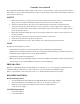
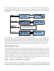
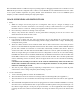
The final system configuration for this exercise will have two C8051F040 processor cards connected to the common CAN bus of the Car Module as well as several wires and cables connected to the Control Module, and Meter Module. The block diagram below shows the required electrical connections among the various components of the exercise. CAN/USB interface to PC running NI LabVIEW tools Figure 2: CAN System Layout Diagram.
the NI_User_Manual file on the MPS web page for details on the procedure to install LabVIEW on your laptop. The studio desktops have the software installed but it will be extremely helpful and instructive for students to have their own copies for this exercise. LabVIEW Interface for Program Development The LabVIEW VIs for the Microprocessor Systems course are designed to send and receive CAN messages to and from the CAN Demo Box and RC car in the lab.
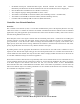
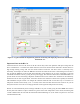
Figure 4: The CAN-viewer-MPS.vi front panel for monitoring and displaying CAN bus information. After becoming familiar with both of these VIs and their block diagrams, one of the objectives of PART II is the development of an enhanced monitoring program that displays the rest of the car data. On possible example is shown below.
Figure 5: A typical student-developed front panel for monitoring and displaying all CAN bus information from the RC car. Important Notes on the RC Car All the functions on the car work, however the drive motor may cause some problems. The input voltage must be above a threshold of ~1.3V before the wheels will turn, and even at that the wheels will need to be kick-started. A high enough starting voltage will start the wheels without a kick-start.
PART III - C Programming: Separate Control Module and Meter Module In this portion of the lab, write a simple program which will turn on the car’s headlights by sending a CAN message containing the bytes 0x0001 with ID 0x01. This will require use of the can_init( ), can_get_tx_buf( ), can_set_address_std( ), can_set_buffer_data( ), can_send_tx_buf( ), and can_send_rtr( ) functions.
The C8051F040 still has a UART0 serial port for printing output or debugging information on a terminal. As in all MPS labs the port must be configured with a counter to set the BAUD rate. The C8051F040 does not have a PLL so the crystal oscillator frequencies are greatly limited. After initialization switch to the 22.1184MHz crystal frequency to reduce confusion and keep the setup option simple. USAGE GUIDELINES AND INSTRUCTIONS 1. Safety a.
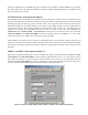
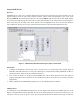
Using LabVIEW 2011 Overview LabVIEW has two main views, the block diagram and the front panel. The front panel can be thought of as the graphical display where the user interacts directly with the system, and the block diagram as the “code” itself. Pressing CTRL+E will switch between these two views and CTRL+T will tile them side-by-side. Right-clicking on the front panel will bring up the menu where controls and indicators can be added. This is shown in Figure 7 below.
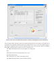
that makes the most sense to display the given data must be chosen. Again, choices can be made based on the data dictionary. Figure 8 shows the block diagram with the highlighted option to add a new blank case. Figure 8: Adding A New Sensor in the Case Structure.
Hardware Setup (PARTS II & III) The following is a detailed description of device hardware setup. Please follow steps in order to ensure proper device function. 1) Identify the 2 twisted-pair power cables from the car. Each pair has a red and black pair, with the red being labeled with the proper voltage that it needs to be plugged into. The black plug corresponding to the red plug is ground. Similarly the black plug accompanying the +5V red plug is also ground.
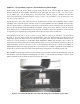
Figure 11: NI USB Connection with CAN MCU 4) The 8051 development boards need to be plugged into the control and meter box modules to ensure the proper delivery and receiving of CAN information. Each 10-pin connector from the modules should be plugged in such that Pin #1 aligns with the corresponding Pin #1 on the port of the MCU. If this has been plugged in correctly, the ribbon should be facing towards the power connection of the board. The red stripe indicates pin 1 on the left side.
speed. This example uses P3 but users may choose to use a different port. The 10 pin connector (on P3) reads in values as follows (all are active low logic signals): 1. Headlights (P3.0) 2. Right turn signal (P3.1) 3. Left turn signal (P3.2) 4. Buzzer (P3.3) 5. Not Used (P3.4) 6. Not Used (P3.5) 7. Not Used (P3.6) 8. Not Used (P3.7) 9. Port power (+3.3V) 10. Ground Figure 13: Control Module Figure 14: Control Module Connection with C8051 Development Board.
1. 2. 3. 4. 5. 6. 7. 8. 9. 10. Not Used (UART0 TX) Not Used (UART0 RX) Temperature (PWM signal) Not Used Turn left signal Turn right signal Not Used Not Used Port power (+3.3V) Ground (P0.0) (P0.1) (P0.2) (P0.3) (P0.4 & low active logic signal) (P0.5 & low active logic signal) (P0.6) (P0.7) The cable with the dashed red stripe is for the DAC outputs. Only the middle two pins are used (J11-3 & 4). These are for DAC0 and DAC1 respectively.
8) After All Modules have been connected properly, place the large plastic cover over the inner parts of the car. The plastic cover should ideally be screwed on to discourage the students from tampering with the inner workings. Figure 17: RC Car Cover The following is a complete Wired Block Diagram for the CAN System. It includes the National Instruments USB 8473 Connection Device that is detailed in the NI Hardware Manual.
APPENDIX A: CAN Addresses Full documentation is available on the web at: http://www.rpi.edu/dept/ecse/mps/mps_handouts.html The CAN interface on the car will receive messages with several message IDs: 0x01: Headlights. This message should contain 2 data bytes. These data bytes represent the desired state of the headlights on the car. 0x0000 turns the headlights off, and any non-zero value turns them on. 0x02: Left Turn Signal. The format of this message is identical to that for 0x01: Headlights.
Table 1: Car Controller Command Functions (& specifications for potentiometers outputs) Function Message ID Data Headlights 0x01 2 bytes: 0=Off 1=On Left Turn Signal 0x02 2 bytes: 0=Off 1=On Right Turn Signal 0x03 2 bytes: 0=Off 1=On Horn 0x04 2 bytes: 0=Off 1=On Drive Motor 0x05 2 bytes: 0 - 4095 Steering Servo Motor 0x06 2 bytes: 0 – 4095 but must be mapped to range: 850 (fully right) - 2150 (fully left) Table 2: Car Meter Monitor Functions (specifications for analog meters) Function
APPENDIX B: Module Pin-outs & Signal Scaling The C8051F040 development boards need to be plugged into the Control and Meter Modules to correctly send and receive CAN information. Each 10-pin connector should be placed on the pins such that pin 1 of the connector aligns with pin 1 of the port (except for the DAC, see 2b below. This corresponds to having the end of the connector with the ribbon on it facing the side that the power to the board comes in on. 1.
APPENDIX C: Pseudo-Programming Example /* * Note that these examples do not include everything necessary for fully * working CAN. It is necessary to set up the crossbar and system clock * correctly in order for the CAN module to work properly. * If terminal printing is desired UART0 with a timer for BAUD rate is needed. */ /* Example CAN Transmission Code */ /* This will send a 3-byte message (0x12 0x34 0x56) to 10-bit address 0x123 */ #include "can.h" /* ...
APPENDIX D: RC Car CAN Arbitration IDs, Functions, and Value Ranges !"#$%"&'()" C"(J5$4?9E >"K&6+I,&3$4,(5 <$4?9&6+I,&3$4,(5 C.I, 21/&&&&&&& !(9(& 3()85$,4& =79"& *+,%-., <(9" >",49? !(9(978" /0'&1! 3$4,(5&678" 6:;<: !"#$%&'(%'()*+,-'&.%/$% 2"&3"&%%%%% /#%/0 1 4,-%5/+&)-( 67 8 922: E)F(.%G#/$&%)$*%#()#% 2"&3"&%%%%% +(H%+,-'&%I+,$F%)&%1%J@ 8 4,-%5/+&)-( 67 8 922: E)F(.%G#/$&%)$*%#()#% 2"&3"&%%%%% #,-'&%+,-'&%I+,$F%)&%1%J@ K 4,-%5/+&)-( 67 8 922: !"#$.