
User`s guide
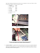
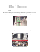
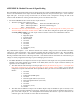

8) After All Modules have been connected properly, place the large plastic cover over the inner parts of the
car. The plastic cover should ideally be screwed on to discourage the students from tampering with the
inner workings.
Figure 17: RC Car Cover
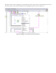
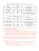
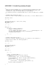
The following is a complete Wired Block Diagram for the CAN System. It includes the National Instruments USB
8473 Connection Device that is detailed in the NI Hardware Manual.
Figure 18: Wiring Block Diagram