
User`s guide

Rev. 0.1 12/05 Copyright © 2005 by Silicon Laboratories C8051F34x-DK
C8051F34x-DK
C8051F34X DEVELOPMENT KIT USER’S GUIDE
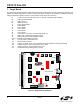
1. Kit Contents
The C8051F34x Development Kit contains the following items:
• C8051F340 Target Board
• C8051Fxxx Development Kit Quick-start Guide
• C8051F34x Development Kit User’s Guide (this document)
• Silicon Laboratories IDE and Product Information CD-ROM. CD content includes:
• Silicon Laboratories Integrated Development Environment (IDE)
• Keil 8051 Development Tools (macro assembler, linker, evaluation ‘C’ compiler)
• Source code examples and register definition files
• Documentation
• AC to DC Power Adapter
• 6’ USB Cable
• Debug Adapter. Items include:
• USB Debug Adapter (USB to Debug Interface)
• USB Cable
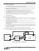
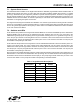
2. Hardware Setup using an EC2 Serial Adapter
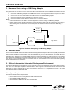
Connect the target board to a PC running the Silicon Laboratories IDE via the Serial Adapter as shown in Figure 1.
1. Connect one end of the RS232 serial cable to a serial (COM) port on the PC.
2. Connect the other end of the RS232 serial cable to the DB-9 connector on the Serial Adapter.
3. Connect the Serial Adapter to the DEBUG connector on the target board using the 10-pin ribbon cable.
4. Connect the AC/DC power adapter to power jack P1 on the target board.
Notes:
•Use the Reset button in the IDE to reset the target when connected using an EC2 Serial Adapter.
• Remove power from the target board and the EC2 before removing the ribbon cable from the target board.
Connecting or disconnecting the cable when the devices have power can damage the device and/or the EC2.
Figure 1. Hardware Setup using an EC2 Serial Adapter
Serial Port
Serial
Adpater
Ribbon Cable
Target Board
AC/DC
Adapter
Serial
Cable
PC