
- Silicon Laboratories, Inc. Computer Accessories User Manual

Rev. 0.1 8/06 Copyright © 2006 by Silicon Laboratories USB Debug Adapter
USB Debug Adapter
USB DEBUG ADAPTER USER’S GUIDE
1. Contents
The USB Debug Adapter package contains the following items:
• USB Debug Adapter (USB to Debug Interface) with attached 7” Ribbon Cable
2. USB Debug Adapter Specifications
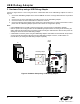
The USB Debug Adapter provides the interface between the PC’s USB port and the target device’s in-system
debug/programming circuitry. The attached 10-pin DEBUG ribbon cable connects the adapter to the target board
and the target device’s debug interface. The USB Debug Adapter supports both Silicon Laboratories JTAG and C2
debug interfaces. Power is provided to the adapter from the USB connection to the PC. The USB Debug Adapter is
capable of providing power to a circuit board via pin 10 of the DEBUG connector. See the Kit User’s Guide for
instructions on powering a target board from this source. Table 1 shows the pin definitions for the DEBUG ribbon
cable connector.
Notes:
• The USB Debug Adapter requires a target system clock of 32 KHz or greater.
• With the default settings, the USB Debug Adapter can supply up to 100 mA to a target system.
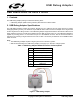
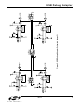
Figure 1. USB Debug Adapter
Table 1. USB Debug Adapter DEBUG Connector Pin Descriptions
Pin # Description
1,8 Not Connected
2,3,9 GND (Ground)
4TCK (C2D)
5TMS
6TDO
7TDI (C2CK)
10 USB Power