Ethernet-DK E MBEDDED E THERN ET D EVELOPMENT K I T U SER ’ S G UIDE 1. Overview The Embedded Ethernet Development Kit (Ethernet-DK) provides all the hardware and software required to develop real-world embedded Ethernet applications using the industry proven CMX Micronet™ protocol stack and high-performance Silicon Laboratories microcontrollers. The TCP/IP protocol stack is developed specifically for embedded processors and is freely distributed in an easy-to-use library.
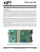
Ethernet-DK 2. Kit Contents The Embedded Ethernet Development Kit contains the following items: C8051F120 Target Board AB4 Ethernet Development Board CAT5e Ethernet Cable Silicon Laboratories Evaluation Kit IDE and Product Information CD-ROM.
Ethernet-DK 3. Hardware Setup The following instructions illustrate how to setup the hardware included with the kit. 1. Connect the AB4 Ethernet Development Board to the C8051F120 Target Board at J24 (Figure 2). Apply slight pressure to ensure the mating 96-pin connectors are firmly connected. 2. Using the ribbon cable, connect the USB Debug Adapter to the C8051F120 Target Board at the JTAG header as shown in Figure 3. 3.
Ethernet-DK 4. Network Setup The Embedded Ethernet Development Kit can be connected to an Ethernet network using a standard Ethernet cable (see Figure 4) or directly to a PC using a crossover cable (see Figure 5). Table 1 describes the benefits of using each of the connection methods. A standard Ethernet cable is included in the kit and crossover cables are available for order from the Silicon Laboratories website, at www.silabs.com.
Ethernet-DK 4.1. Network Setup Procedure If using a standard cable: 1. Connect the AB4 Ethernet Development Board to an Ethernet wall outlet or to a router/switch using a standard Ethernet cable. 2. Connect a PC to the same Ethernet network using a standard Ethernet cable. If using a crossover cable: 1. Connect the AB4 Ethernet Development Board directly to a PC using an Ethernet crossover cable. 2. Configure the PC to have a static IP address.
Ethernet-DK 4.2. Selecting an IP Address for the Embedded System For a PC to recognize an embedded system on a network, its IP address and subnet mask need to be configured. Below are a few guidelines to follow when choosing an IP address for the embedded system. Figure 6 shows an example of a compatible PC and embedded system IP address combination. 1. Find the IP address and Subnet mask for the PC. If a Default Gateway is specified, then save this address for later use.
Ethernet-DK 5. Software Setup The included CD-ROM contains the Silicon Laboratories IDE, Keil C51 toolset, and documentation including datasheets, application notes, and an electronic version of this user’s guide. The instructions below describe how to install the Embedded Ethernet Development Kit software. Refer to the readme.txt file on the CD-ROM for the IDE release notes containing the latest information regarding supported devices, revision history, and known issues. 1.
Ethernet-DK 4. Unselect the “Install Raisonance Evaluation 8051 Toolset” option and select “Install Keil Evaluation 8051 Toolset”. Then press the Install button. 5. Follow the installation prompts to install the development tools. The following applications will be installed: The Silicon Laboratories IDE will be installed by default in the C:\SiLabs\MCU directory. Embedded Ethernet examples will be installed by default in the C:\SiLabs\MCU\Examples\C8051F12x\Ethernet directory.
Ethernet-DK 6. Embedded Ethernet Tutorial Now that the Embedded Ethernet Development Kit hardware has been set up, the software installed, and the embedded system connected to a network, it is time to download firmware into the MCU and test its network connectivity. The Embedded Ethernet Tutorial consists of four stages of increasing functionality and will allow the user to quickly learn how to use the development kit hardware and software. 6.1.
Ethernet-DK 5. In the System Settings section of the left window, select IP Addresses. 6. In the right window, set the Source IP Address to the IP address of the embedded system. 7. If the Gateway IP Address and Subnet mask of the network are known, then fill in the addresses on the right window (see Figure 8). 8. If using the CP2200, the MAC address field is ignored. The CP2200 Ethernet Controller contains a unique factory-programmed MAC address stored in Flash memory. Figure 8.
Ethernet-DK 9. Save the selected configuration using the FileSave As menu. 10. Generate a new project with supporting firmware by selecting Generate Project from the File menu (see Figure 9). 11. When prompted for a folder to save the project, browse to an empty directory or create a new directory. Note: Any files in the selected directory will be overwritten. Click the OK button. 12. Click the OK button when the “Project generated successfully” message appears. 13. Close the TCP/IP Configuration Wizard.
Ethernet-DK 6.1.2. Programming the MCU We will now build the project created by the TCP/IP Configuration Wizard and download the firmware to the MCU using the Silicon Laboratories IDE. 1. From the Windows Start menu, start the Silicon Laboratories IDE. The shortcut will be under the StartSilicon Laboratories menu. Alternatively, the Silicon Labs IDE can be started by double-clicking IDE.exe located by default in the “C:\SiLabs\MCU” directory. 2.
Ethernet-DK 5. Verify the Compiler and Linker tabs are pointing to the C51.exe (compiler) and BL51.exe (linker) files in C:\Keil\C51\BIN in the Executable field. 6. Press the Compiler tab's Customize button. Under the Variable Location drop down box, select Large: XDATA and press OK. Then press OK to close the Tool Chain Integration dialog. 7. Build the project.
Ethernet-DK 8. Click the Connect button in the toolbar or select DebugConnect from the menu. Note: If you receive the error message “Communication could not be established with the specified serial adapter”, open the Connection Options Dialog by selecting OptionsConnection Options from the menu. Verify that the USB Debug Adapter is selected and that the debug interface is set to JTAG. 9. Download the project to the target by clicking the Download Code button in the toolbar. 10.
Ethernet-DK 6.1.3. Testing Connectivity Using PING After pressing GO, the MCU will be executing the TCP/IP stack firmware. The LEDs on the RJ-45 Ethernet connector should light up if the MCU is connected to a network. Once the network router detects the presence of the embedded system, it will be accessible from any PC connected to the same network. This usually takes a few seconds, but can take over 30 seconds depending on the size of the network.
Ethernet-DK 6.2. Stage 2—Basic Web Server with DHCP and Netfinder Capability In the first stage of the demo, we learned how to generate firmware for an embedded web server using the TCP/IP Configuration Wizard and access the embedded server from a web browser. In this stage, we will learn how to generate a web server that uses automatic network configuration (DHCP) to automatically obtain an IP address from the network. We will also find the embedded web server on the network using the Netfinder utility.
Ethernet-DK 5. Save the selected configuration using the FileSave As menu. 6. Generate a new project with supporting firmware by selecting Generate Project from the File menu (see Figure 13). 7. When prompted for a folder to save the project, browse to an empty directory or create a new directory. Note: Any files in the selected directory will be overwritten. Click the OK button. 8. Click the OK button when the “Project generated successfully” message appears. 9. Close the TCP/IP Configuration Wizard.
Ethernet-DK 6.2.2. Programming the MCU We will now build the project created by the TCP/IP Configuration Wizard and download the firmware to the MCU using the Silicon Laboratories IDE. 1. From the Windows Start menu, start the Silicon Laboratories IDE. The shortcut will be under the StartSilicon Laboratories menu. Alternatively, the Silicon Labs IDE can be started by double-clicking IDE.exe located by default in the “C:\SiLabs\MCU” directory. 2.
Ethernet-DK 5. Verify the Compiler and Linker tabs are pointing to the C51.exe (compiler) and BL51.exe (linker) files in C:\Keil\C51\BIN in the Executable field. 6. Press the Compiler tab's Customize button. Under the Variable Location drop down box, select Large: XDATA and press OK. Then press OK to close the Tool Chain Integration dialog. 7. Build the project.
Ethernet-DK 8. Click the Connect button in the toolbar or select DebugConnect from the menu. Note: If you receive the error message “Communication could not be established with the specified serial adapter”, open the Connection Options Dialog by selecting OptionsConnection Options from the menu. Verify that the USB Debug Adapter is selected and that the debug interface is set to JTAG. 9. Download the project to the target by clicking the Download Code button in the toolbar. 10.
Ethernet-DK 6.2.3. Finding the Embedded System We will now search for embedded systems on the network. Note: The Netfinder utility v1.0 is not compatible with Windows Vista or Windows 7. 1. Open the Netfinder utility found in C:\SiLabs\MCU\Utilities\Netfinder. 2. Press the Search button as shown in Figure 14 to begin searching for devices. Figure 14. Search Button 3. The Embedded System should appear inside a box with a green background.
Ethernet-DK 5. The default web browser should launch and display the home page served by the embedded web server. The same result can be achieved by typing the IP address of the embedded web server into the address bar of a web browser. Figure 16 shows a screenshot of the home page. Now go directly to Section "6.3. Stage 3—Configuring MAC and IP Addresses over the Serial Port" on page 25. Figure 16. Hello World Web Page 6.
Ethernet-DK 7. Enter the IP address, subnet mask, and default gateway (if known) into the ‘Assign IP Address’ dialog and press OK. See Appendix A for information on how to configure the PC with a static IP address and how to select a static IP address for the CP2201EB. A windows command line window should appear, ping the device at its new address, then close. Programming is successful when the progress bar stops and gives the message “Success - Device Programmed” as shown in Figure 18. . Figure 18.
Ethernet-DK 10. The default web browser should launch and display the home page served by the embedded web server. The same result can be achieved by typing the IP address of the embedded web server into the address bar of a web browser. Figure 20 shows a screenshot of the uWeb-v2.0 home page. Figure 20. Hello World Web Page 24 Rev. 0.
Ethernet-DK 6.3. Stage 3—Configuring MAC and IP Addresses over the Serial Port In the first two stages of the demo, we learned how to generate firmware for an embedded web server using the TCP/IP Configuration Wizard and access the embedded server from a web browser. In this stage, we will learn how to dynamically configure the IP address over the serial port. 6.3.1. Configuring the Target Board Jumpers for UART communication.
Ethernet-DK 6.3.3. Programming the IP Address Now the MCU will be running the new firmware and blinking the green LED (P1.6) to indicate that the IP address has not been programmed. In this mode, the MCU is waiting for the user to initiate the update by connecting to the serial port and pressing any key to start. Figure 21 shows the output seen on a UART terminal screen when the MCU is waiting for user input. The following instructions show how to program the IP and MAC addresses. 1.
Ethernet-DK 6.4. Stage 4—Adding Web Server Content In the first three stages of the demo, we learned how to make an embedded web server, find it on the network using Netfinder, and program its IP over the serial port. In this stage, we will learn how to change the HTML content on the server and see an example of an embedded temperature sensing web server (uWeb) that graphs temperature and controls an LED. 6.4.1.
Ethernet-DK 6.4.3. Re-Building the Project and Viewing Results Once the file arrays are updated, it is time to re-build the project and view the results. 1. Open and re-build the project. This can be done by selecting ProjectOpen Project and selecting the correct project, then clicking on the Build/Make Project button in the toolbar, selecting ProjectBuild/Make Project from the menu, or pressing the F7 shortcut key. 2.
Ethernet-DK Figure 26. µWeb Embedded Web Server Rev. 0.
Ethernet-DK 7. Example Source Code The Embedded Ethernet Development Kit includes example source code, libraries, and register definition files for all MCU devices. These examples are installed by default in the “C:\SiLabs\MCU\Examples” directory during IDE installation. Inside this directory, an “Ethernet” folder is included within each device family directory supported by the TCP/IP Configuration Wizard. Each of the examples is described below. 7.1.
Ethernet-DK 8. C8051F120 Target Board The Embedded Ethernet Development Kit includes a target board with a C8051F120 device pre-installed for evaluation and software development. Numerous input/output (I/O) connections are provided to facilitate prototyping using the target board. Refer to Figure 27 for the locations of the various I/O connectors.
Ethernet-DK Figure 28. C8051F120 Target Board Schematic 8.1. C8051F120 Target Board Schematic 32 Rev. 0.
Ethernet-DK 9. AB4 Ethernet Development Board The Embedded Ethernet Development Kit includes the AB4 Ethernet Development Board designed to connect the C8051F120 (or C8051F340, C8051F020, C8051F040, or C8051F060) target board to an ethernet network. The ethernet controller used is the CP2200. Refer to Figure 29 for the locations of the various I/O connectors.
Ethernet-DK 9.1. Expansion I/O Connector (J1) The 96-pin expansion I/O connector J1 is used to connect the AB4 Ethernet Development Board to the C8051F120 Target Board. J1 provides access to many C8051F120 signal pins. Pins for +3 V, digital ground, analog ground and the unregulated power supply (VUNREG) are also available. The VUNREG pin is connected directly to the unregulated +V pin of the P1 power connector on the C8051F120 Target Board. See Table 3 for a complete list of pins available at J1. Table 3.
Ethernet-DK 9.2. AB4 Board Schematic Rev. 0.
Ethernet-DK 10. Silicon Laboratories IDE (Integrated Development Environment) The Silicon Laboratories IDE integrates a source-code editor, source-level debugger and in-system Flash programmer. The use of third-party compilers and assemblers is also supported. This development kit includes the Keil Software A51 macro assembler, BL51 linker, and evaluation version of the C51 compiler. These tools can be used from within the Silicon Laboratories IDE. 10.1.
Ethernet-DK APPENDIX—SUPPORTED PROTOCOLS Link/Physical Layer: Ethernet (IEEE802.3)—Widely installed local area network link/physical layer. Internet Layer: IP (Internet Protocol)—IP specifies the format of packets and manages the addressing of all devices on the network. IP is included in all builds of the TCP/IP stack. PING (Packet Internet Groper)—PING is a basic network program which verifies that a particular IP address exists and can respond to requests.
Ethernet-DK DOCUMENT CHANGE LIST Revision 0.3 to Revision 0.4 Added Netfinder Example. Added note that R1 should be shorted with a zero ohm resistor on the 'F12x Target Board. Updated the supported protocols in the Appendix. Updated screenshots for Version 3.1 of the TCP/IP Configuration Wizard. Revision 0.4 to Revision 0.5 Removed Section 10. USB Debug Adapter. See USB Debug Adapter User's Guide. Revision 0.5 to Revision 0.6 Updated text for v4.0 of the IDE and above.
Ethernet-DK NOTES: Rev. 0.
Ethernet-DK CONTACT INFORMATION Silicon Laboratories Inc. 400 W Cesar Chavez Austin, TX 78701 Please visit the Silicon Labs Technical Support web page: https://www.silabs.com/support/pages/contacttechnicalsupport.aspx and register to submit a technical support request. . The information in this document is believed to be accurate in all respects at the time of publication but is subject to change without notice.