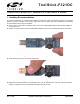
To o l Sti c k - F 3 2 1 D C TO O L S TICK C 8 0 5 1 F 3 2 1 D A U G H T E R C ARD U S E R ’ S G U I D E 1. Handling Recommendations To enable development, the ToolStick Base Adapter and daughter cards are distributed without any protective plastics.
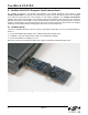
ToolSt ic k- F 321DC 2. Contents The ToolStick-F321DC kit contains the following items: ToolStick C8051F321 Daughter Card A ToolStick daughter card requires a ToolStick Base Adapter to communicate with the PC. ToolStick Base Adapters can be purchased at www.silabs.com/toolstick. 3.
ToolStick-F321DC 4. Getting Started The necessary software to download, debug and communicate with the target microcontroller must be downloaded from www.silabs.com/toolstick. The following software is necessary to build a project, download code to, and communicate with the target microcontroller: Silicon Laboratories Integrated Development Environment (IDE) Keil Demonstration Tools ToolStick Terminal application The Keil Demo Toolset includes a compiler, assembler, and linker. See Section “5.2.2.
ToolSt ic k- F 321DC 5.2. Keil Demonstration Toolset 5.2.1. Keil Assembler and Linker The Keil demonstration toolset assembler and linker place no restrictions on code size. 5.2.2. Keil Demonstration C51 C Compiler The evaluation version of the C51 compiler is the same as the full version with the following limitations: Maximum 4 kB code generation. There is no floating point library included.
ToolStick-F321DC 5.4. Keil uVision2 and uVision3 Silicon Laboratories Drivers As an alternative to the Silicon Laboratories IDE, the uVision debug driver allows the Keil uVision2 and uVision3 IDEs to communicate with Silicon Laboratories on-chip debug logic. In-system Flash memory programming integrated into the driver allows for rapidly updating target code.
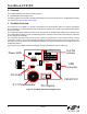
ToolSt ic k- F 321DC 6. ToolStick C8051F321 Daughter Card Features Demo The ToolStick kit includes a few simple code examples. The example described in this section is titled F321DC_FeaturesDemo. The purpose of this example is to guide a new user through the features and capabilities of the IDE and demonstrate the microcontroller’s on-chip debug capabilities. The F321DC_FeaturesDemo example code uses the potentiometer on the daughter card to vary the blinking rate of the LED.
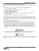
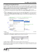
ToolStick-F321DC 6.2. Connecting to the Device and Downloading Firmware This section describes how to open the IDE, open and build a project, connect to a device and download the firmware. 1. Open the Silicon Laboratories IDE from the Start → Programs → Silicon Laboratories menu. 2. In the IDE, go to Project → Open Project. 3. Browse to the default location, C:\SiLabs\MCU\ToolStick\F321DC\Firmware\. 4. Select F321DC_FeaturesDemo.wsp and click OK. 5. In the IDE, select Project → Rebuild Project. 6.
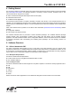
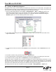
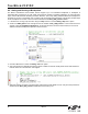
ToolSt ic k- F 321DC 6.4. Viewing and Modifying Registers All registers on the device can be viewed and modified when the device is in a halted state. The registers are grouped together according to which peripheral or part of hardware they belong. As an example, this guide shows how to open the ADC0 Debug Window and disable the ADC0 directly from the IDE. 1. Open the ADC0 Debug Window from the View → Debug Windows → SFR’s → ADC0 menu option. The ADC0 Debug Window appears on the right-hand side of the IDE.
ToolStick-F321DC 6.5. Enabling and Using Watch Windows The Debug Windows in the View menu are used to view and modify hardware registers. To view and modify variables in code, the IDE provides Watch Windows. Just as with register debug windows, variables in the watch windows are updated each time the device is halted. This section of the User’s Guide explains how to add a variable to the watch window and modify the variable.
ToolSt ic k- F 321DC 6.6. Setting and Running to Breakpoints The Silicon Laboratories microcontroller devices support up to four hardware breakpoints. A breakpoint is associated with a specific line of code. When the processor reaches a hardware breakpoint, the code execution stops, and the IDE refreshes all debug and watch windows. The on-chip debug hardware allows for breakpoints to be placed on any line of executable code, including code in Interrupt Service Routines.
ToolStick-F321DC 6.7. Single-Stepping Through Firmware The IDE supports the ability to single-step through firmware one assembly instruction at a time. The IDE reads the Flash from the device, converts the instructions to assembly and displays them in a disassembly window. The following steps show how to open the disassembly window and single step through firmware. 1.
ToolSt ic k- F 321DC 6.8. Using ToolStick Terminal This section describes how to use ToolStick Terminal to communicate with UART from the PC to the daughter card through the ToolStick Base Adapter. 1. If the Silicon Laboratories IDE is open, close the IDE. The IDE and the ToolStick Terminal cannot communicate with the daughter card simultaneously. 2. Open ToolStick Terminal from the Start → Programs → Silicon Laboratories menu. 3. Go to the ToolStick → Settings menu. 4.
ToolStick-F321DC 7. Additional Demo Example In addition to the F321DC_FeaturesDemo example firmware, the ToolStick download package also includes a demo project named F321DC_HIDMouse.wsp. The instructions for running this demo can be found at the top of the source file. The project and source files for these demos can be found in the folder, C:\SiLabs\MCU\ToolStick\F321DC\Firmware\. 8.
ToolSt ic k- F 321DC Figure 6. C8051F321 Daughter Card Schematic 10. C8051F321 Daughter Card Schematic 14 Rev. 0.
ToolStick-F321DC NOTES: Rev. 0.
ToolSt ic k- F 321DC CONTACT INFORMATION Silicon Laboratories Inc. 400 West Cesar Chavez Austin, TX 78701 Tel: 1+(512) 416-8500 Fax: 1+(512) 416-9669 Toll Free: 1+(877) 444-3032 Email: MCUinfo@silabs.com Internet: www.silabs.com The information in this document is believed to be accurate in all respects at the time of publication but is subject to change without notice.