
Specifications


AN93
Rev. 0.8 119
Testing
This section contains information about using the
Si2493/57/34/15/04 built-in self-test features and
suggestions for board-level testing and presents special
test commands and methods useful for regulatory
testing.
Self Test
The Si2493/57/34/15/04’s advanced design provides
the system manufacturer with increased ability to
determine system functionality during production tests
and to support end-user diagnostics. In addition to local
echo, a loopback mode exists allowing increased
coverage of system components. For the loopback test
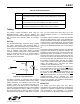
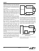
mode, a line-side power source is required. While a
standard phone line can be used, the test circuit in
shown Figure 23 is adequate.
Figure 23. Loop Test Circuit
The AT&Tn command, in conjunction with the AT&Hn
command, performs a loopback self test of the modem.
AT&Hn determines the modulation used for the test
(V.22bis, V.32bis, etc). If an AT&Hn command is not
issued just prior to the start of the test, the default or
previously-selected modulation is used. The modulation
options and defaults are listed in Table 21 on page 39.
The test is started with an AT&T2 or AT&T3 command.
During the test, the modem is in data mode. To end the
test, you must escape data mode using one of the
“Escape” methods, such as “+++”, and end the test with
AT&T0.
The AT&T2 command initiates a test loop from the DSP
through the DAA interface circuit of the Si2493/57/34/
15/04. Transmit data is returned to the DSP through the
receive channel. In the parallel mode, the transmit data
is passed to the receiver via Parallel Register 0. AT&T2
tests only the Si2493/57/34/15/04 chip, not the Si3018/
10.
The AT&T3 command initiates a test loop from the DSP
through the DAA interface, the ISOcap™ interface, the
Si3018/10, and the hybrid circuit. This test exercises the
Si2493/57/34/15/04, the Si3018/10, and many of the
external components. A phone line termination with loop
current and no dial tone is required for this test since it
involves the line-side chip (Si3018/10) and the hybrid.
The modem is off-hook during this test. The AT&T3
mode is useful during emitted and conducted radiation
testing. Set U62(DL) [1] = 1, and issue the AT&T3
command to test the ISOcap link only.
The AT\U command is also useful as a production test.
This command places a 25 ms low pulse on RI
(Si2493/
57/34/15/04, pin 17) and DCD
(Si2493/57/34/15/04,
pin 23). It also makes INT
(Si2493/57/34/15/04, pin 16)
the inverse of ESC (Si2493/57/34/15/04, pin 22) and
RTS
(Si2493/57/34/15/04, pin 8) the inverse of CTS
(Si2493/57/34/15/04, pin 11). Sending the AT\U
command can be used to verify the connection of these
pins to the circuit board. This command is terminated by
resetting the Si2493/57/34/15/04.
Board Test
The modem and DAA chips come from Silicon
Laboratories 100% functionally tested on automatic test
equipment to guarantee compliance with the published
chip specifications. The functionality of a finished
product containing an ISOmodem chipset depends on
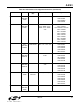
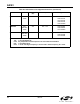
Table 86. AT+PSS Parameters
<value> Description
0 The DCEs decide whether or not to use the short startup procedures. The
short startup procedures shall only be used if enabled by the +PQC com-
mand.
1 Forces the use of the short startup procedures on the next and subse-
quent connections if they are enabled by the +PQC command.
2 Forces the use of the full startup procedures on the next and subsequent
connections independent of the setting of the +PQC command.
I
L
10 µF
600 Ω
TIP
+
–
RING
V
TR
Si3018
>20 mA