
Specifications


AN93
Rev. 0.8 125
Table 92 shows the AT command string that configures
the ISOmodem for Japan caller ID.
The following sections describe each CID mode.
US Bellcore Caller ID
The ISOmodem detects the first ring burst, echoes
“RING” to the host, and prepares to detect the CID
preamble. If +VCID = 2, 50 continuous mark bits (1s)
are detected, the “CIDM” response is echoed to the host
(indicating the mark sequence was received and FSK
modulated CID data will follow), and INT
is triggered if
enabled. Next the CID algorithm looks for the start bit,
assembles the characters, and sends them to the host
as they are received. When the CID burst is finished,
the carrier is lost, and “NO CARRIER” is echoed to the
host. The ISOmodem continues to detect subsequent
ring bursts, echoes “RING” to the host, increments the
ring counter, S1, and automatically answers after the
number of rings specified in S0.
Forced Caller ID
In this mode, the ISOmodem continuously monitors TIP
and RING while on-hook for the CID mark sequence
and FSK data. This mode is useful in systems requiring
detection of CID data before the ring burst. It is also
useful for detecting voice mail indicator signals and for
supporting Type II Caller ID.
UK Caller ID
The ISOmodem first detects a line polarity reversal,
echoes “FLASH” to the host, and triggers the INT
pin.
The ISOmodem then searches for the Idle State Tone
Alert signal and when detected echoes “STAS” to the
host. After the Idle State Tone Alert Signal is completed,
the ISOmodem goes off-hook then on-hook to apply the
15 ms wetting pulse to the local loop. Next, the
ISOmodem prepares to detect the CID preamble. After
50 continuous mark bits (1s) are detected, the “CIDM”
response is echoed to the host indicating the mark
sequence was received and FSK modulated CID data
will follow, and INT
is again triggered. Then, the CID
algorithm looks for the start bit, assembles the
characters, and sends them to the host as they are
received. When the CID burst is finished, the carrier is
lost, and “NO CARRIER” is echoed to the host. The
ISOmodem detects ring bursts, echo “RING” to the host,
increment the ring counter, S1, and automatically
answer after the number of rings specified in S0.
Japan Caller ID
The ISOmodem detects a line polarity reversal and a
brief ring burst, then goes off-hook and triggers the INT
pin. CID data is sent using the V.23 specification. After
detecting 40 mark bits (1s), the ISOmodem searches for
a start-bit. “CIDM” is echoed to the host when a start bit
is received. The modem then starts to assemble
characters and sends them to the host. When the CID
signal is lost, the ISOmodem hangs up and echoes “NO
CARRIER” to the host. The modem then waits for the
normal ring signal.
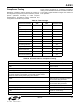
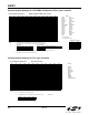
Table 92. Japan Caller ID
Command Function
AT+VCID = 1 Enables caller ID.
AT+VCDT = 3 Selects Japan CID mode.
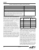
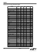
Table 93. International Call Progress Registers
Register Value Function
Dial Tone Control
U0–U14 Dial Tone Detect Filter
Coefficients
U15 DTON Dial Tone On Threshold
U16 DTOF Dial Tone Off Threshold
U34 DTWD Dial Tone Detect Window
U35 DMOT Dial Tone Minimum On
Time
Busy Tone Control
U17–U2B Busy Tone Detect Filter
Coefficients
U2C BTON Busy Tone On Threshold
U2D BTOF Busy Tone Off Threshold
U2E BMTT Busy Tone Minimum Total
Time
U2F BDLT Busy Tone Delta Time
U30 BMOT Busy Tone Minimum On
Time
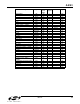
Ringback Cadence Control
U31 RMTT Ringback Tone Minimum
Tota l Ti me
U32 RDLT Ringback Tone Delta Time
U33 RMOT Ringback Tone Minimum
On Time
Ring Detect Control
U49 RGFH Ring Frequency High
U4A RGFD Ring Frequency Delta
U4B RGMN Ring Cadence Minimum On
Time
U4C RGNX Ring Cadence Maximum
Tota l Ti me