
Specifications


AN93
160 Rev. 0.8
within 200 ms after the carriage return. The reset
recovery time (the time between a hardware reset or
the carriage return of an ATZ command and the time
the next AT command can be executed) is
approximately 300 ms. When a data connection is
being established, do not try to escape to the
command mode until after the protocol message.
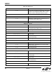
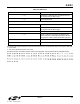
Register Configurations
The ATS$ command lists the contents of all S-
Registers, and the AT:R command lists the contents
of all U-Registers.
Si3018/10 and/or Associated Components
If the modem goes off-hook and draws loop current
as a result of giving the ATH1 command, go to the
Si3018/10 Troubleshooting section.
If the modem does not go off-hook and draw loop
current as a result of giving the ATH1 command and
receiving an “OK” message, begin troubleshooting
with the ISOcap™ at the Si2457/34/15. First check
all solder joints on the ISOcaps, Si3018/10, and
associated external components. If no problems are
found, proceed to the following ISOcap
Troubleshooting section to verify whether the
problem is on the Si2493/57/34/15/04 or the Si3018/
10 side of the ISOcap. If the problem is found to be
on the Si2493/57/34/15/04 side, check C50, C51,
C53, the corresponding PCB traces, and Si2493/57/
34/15/04 pins. Correct any problems. If no problems
are found with the external components, replace the
Si2457/34/15.
If the problem is found to be on the Si3018/10 side of
the ISOcap, go to the Si3018/10 Troubleshooting
section.
The modem does NOT respond with an “OK” to the
command ”AT<cr>.”
This indicates the host processor/software is not
communicating with the modem controller, and the
problem can be isolated as follows.
Si2493/57/34/15/04 Clock is Oscillating
First be sure the Si2493/57/34/15/04 is properly
reset and RESET
, pin 12, is at 3.3 V. Next, check the
DTE connection with the host system. If this does
not isolate the problem, go to the Host Interface
Troubleshooting section.
Si2493/57/34/15/04 Clock is Not Oscillating
Check the voltage on the Si2493/57/34/15/04, pins 5
and 21, to be sure the chip is powered. Also, check
that pins 6 and 20 are grounded. Next, check the
solder joints and connections (PCB traces) on C40,
C41, Y1 and the Si2493/57/34/15/04 pin 1 and pin 2.
Measure C26 and C27 (or replace them with known
good parts) to ensure they are the correct value. If
these steps do not isolate the problem, replace the
Si2457/34/15.
Host Interface Troubleshooting
The methods described in this section are useful as a
starting point for debugging a prototype system or as a
continuation of the troubleshooting process described
above. The procedures presented in this section require
a known good Si2457/34/15URT-EVB evaluation board
and data sheet. This section describes how to substitute
the evaluation board for the entire modem circuitry in
the prototype system. Substituting a known operational
modem can help to quickly isolate problems. The first
step is to substitute the evaluation board for the
complete modem solution in the prototype system. This
demonstrates immediately whether any modem
functionality problems are in the prototype modem
circuitry or in the host processor, interface, or software.
Verify Si2457/34/15URT-EVB Functionality
Connect the evaluation board to a PC and a phone
line or telephone line simulator. Using a program
such as HyperTerm, make a data connection
between the evaluation board and a remote modem.
Remove power and the RS232 cable from the
evaluation board and proceed to the next step.
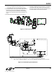
Connect Evaluation Board to Prototype System
Completely disconnect the embedded modem from
the host interface in the prototype system. Connect
the Si2457/34/15URT-EVB to the host interface
using JP3 as described in the Si2457/34/15URT-
EVB data sheet section titled Direct Access
Interface. This connection is illustrated in Figure 30.
Be sure to connect the evaluation board ground to
the prototype system ground. Power up and
manually reset the evaluation board then power up
the prototype system and send “AT<cr>.” If an “OK”
response is received, make a connection to the
remote modem as in the previous step. If no “OK”
response is received, debug host interface and/or
software. If a connection is successfully made, go to
the next step to isolate the problem in the prototype
modem.
An alternative approach is to connect the prototype
modem to the Si2457/34/15URT-EVB motherboard
in place of the daughter card and use a PC and
HyperTerm to test the prototype modem. See Figure
Figure 31 for details.
ISOcap™ Troubleshooting
Connect Evaluation Board ISOcap to Prototype Modem
Si3018/10. Remove C1 on the evaluation board and on
the prototype system. Solder one end of the evaluation
board, C1, to the Si2457/34/15-side pad leaving the
other end of C1 unconnected. Next, solder a short
jumper wire from the unconnected side of C1 on the