
Specifications


AN93
Rev. 0.8 23
V.80 Mode
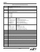
As shown in Table 13, the synchronous access mode is
chosen by using the AT+ES=6,,8 command setting.
When using the synchronous access mode, it is
expected that the AT\N0 command be used to disable
all other error correction protocols that may interfere
with V.80 synchronous access mode operation.
The V.80 Mode has two distinct submodes. Switching
between these two submodes can be accomplished
within the confines of the same connection through the
use of In-Band commands.
Transparent Submode
Framed Submode
The Transparent Submode creates a direct bit-by-bit
translation from the DTE to and from the DCE. Any
application that requires a method of reconstructing a
serial bit-stream at the DCE can use the Transparent
Sub-mode.
The Framed Sub-mode represents data at the DCE in
HDLC/SDLC frames. This submode is typically used in
Point-of-Sale Terminal Applications. A common feature
used in conjunction with the Framed Submode is the
use of the 16-bit CRC. When used with the CRC option,
the Framed Submode can be used in the same
applications currently using the Legacy Synchronous
DCE Mode.
Prior to sending the ATDT to establish a synchronous
access mode connection, the following commands and
registers require initialization: +MS, +ES, +ESA, +ITF,
+IFC, U87 and U7A.
As an example, the closest equivalent to the Legacy
Synchronous DCE Mode is the following initialization
setting.
With either Synchronous Access Submode, once a
connection has been established, payload data is
multiplexed with command / indicator information by use
of <EM> shielding. With <EM> shielding, either of the
two bytes <0x19> or <0x99>, used to represent <EM>,
precedes a special command, or special indicator.
Note that the synchronous access mode <EM>
shielding is designed to support XON/XOFF
handshaking. As such, the bytes 0x13 and 0x11 (XON/
XOFF) are considered to be special characters in the
same way the 0x19 and 0x99 bytes, used for <EM>, are
special.
Since the payload data is multiplexed with <EM>
shielded command/indicator and possibly XON/XOFF
characters, Transparency <EM> codes are defined for
the purpose of allowing the host software to send 0x13,
0x11, 0x19 and 0x99 bytes to/from the DCE. For
example, if the desire is to send one <0x99> character
as a payload character, the host software sends
<EM><0x76> instead.
For a complete set of the <EM> command/status see
Table 15.
In addition, a common Point-of-Sale V.22 Fast Connect
Handshake Protocol (with transparent HDLC) requires
these additional settings:
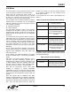
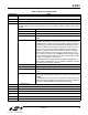
Table 13. Synchronous Access Mode Settings
AT\N0 Required to disable MNP,V42
and other protocols
AT+ES = 6,,8 Enable synchronous access
mode on originate or answer
AT+ESA = 0,0,0,,1,0 Send Abort on underrun/over-
run in Framed Submode.
Enable CRC generation and
checking.
AT+IFC = 2,2 CTS/RTS Flow Control
AT+ITF = 0383,0128 Controls CTS Flow Control
Threshold. CTS off at 383
bytes, CTS On at 128 bytes.
AT:U87,010A Direct to Framed Sub-mode
upon connection. DCE starts to
transmit upon receipt of 10
bytes from the DTE.
Table 14. Fast Connect Settings
AT+MS = V22 V22 Protocol
AT:U7A,3 Set Fast Connect, Transmit
HDLC Flags instead of Marks
during handshake negotiation.