
Specifications


AN93
Rev. 0.8 25
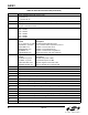
Given the example initialization settings shown in
Table 14, after an ATDT command has been sent to
establish a connection, the modem responds with the
following.
ATDT12345
CONNECT 1200
PROTOCOL: NONE
<0x19> <0xBE> <0x20> <0x20> <0x19> <0xB1>
The first <EM><rate> indicator shows that the modem
connected with a TX rate of 1200 bps, and an RX rate of
1200 bps. The <EM><flag> that occurs immediately
after the <EM><rate> indicates that a non-flag to flag
transition has occurred, and that the receiver has now
been synchronized. Note that an <EM> <flag> indicator
is applicable only to the first occurrence of a non-flag to
flag transition. Future occurrences of non-flag to flag
transitions are indicated with an <EM> <err> instead.
Also, this feature is unique to the U87[8]=1 option. Also
note that with U87[8]=1, the Framed Submode is
entered immediately upon connection. Otherwise, if
U87[8]=0, the Transparent Submode is entered instead,
and the host is expected to send an <EM> <flag> to
switch to the Framed Submode.
After a connection has been established, the modem is
ready to transmit and receive frames. For example, if it
is desired to send a frame whose contents are:
<0x10><0x11><0x12><0x13><0x14> <0x15>
The host software sends this:
<0x10><0x19><0xA0><0x12><0x19><0xA1><0x14><
0x15><0x19><0xB1>
Note the bytes <0x11> and <0x13> are <EM> shielded
because these bytes could have been used for XON /
XOFF handshaking. In this example, CTS/RTS
hardware handshaking is used, so it is also possible for
the host to have sent this series of bytes instead:
<0x10><0x11><0x12><0x13><0x14><0x15><0x19><0
xB1>
However, if the host does not <EM> shield the 0x11 and
0x13 characters, XON / XOFF software handshaking
can no longer be used.
In either of the above transmit frames, the <EM> <flag>
is used to indicate that a logical frame has completed.
The modem does not begin transmitting the frame at the
DCE until the <EM> <flag> is received, or if the number
of bytes sent to the modem exceeds the number of
bytes programmed into U87[7:0].
In the above example, the transmission:
<0x10><0x19><0xA0><0x12><0x19><0xA1><0x14
><0x15><0x19><0xB1>
meets BOTH the criteria of having 10 bytes received at
the DTE, and receipt of an <EM> <flag> command. In
this example, the transmission at the DCE begins
approximately after the receipt of the <0xB1> byte.
Once an HDLC frame begins transmitting at the DCE,
the host must ensure transmit overruns and underrun
do not occur. It is expected that the +ITF command be
used to adjust the transmit flow control thresholds so
that it is tuned to the system's ability to process the
interrupt.
If a transmit underrun occurs, the <EM> <tunder>
indicator always appears in the receive path, regardless
of how +ESA[C] is programmed.
If +ESA[C] = 0, the modem transmits an abort character
at the DCE, at the point of the transmit underrun.
Additional transmit frames can then be transmitted
normally.
If +ESA[C] = 1, the modem transmits an HDLC flag at
the point of the transmit underrun, and the DCE
continues to send only HDLC flags until the host sends
an <EM> <resume> command. The <EM> <resume> is
then followed by the <EM> <unum> command so that
the host software can correct this problem.
A transmit overrun can occur if the host does not
properly implement transmit flow control. When a
transmit overflow occurs, the <EM> <tover> indicator
always appears in the receive path. A transmit overflow
is considered to be a catastrophic failure, and results in
non-deterministic behavior at the DCE. It is
recommended that the session be terminated
immediately.
It is expected that the <EM> <tover> and <EM>
<tunder> indicators be encountered during system
debug, and designing the system software properly to
avoid having these indicators occur should be the
design goal.
In the receive direction, assuming that the remote
modem is another Si2457/34/15, this is the expected
sequence at the remote receiver DTE, representing the
frame sequence of
<0x10><0x11><0x12><0x13><0x14> <0x15>.
<0x10><0x19><0xA0><0x12><0x19><0xA1><0x14><
0x15><0x19><0xB1>
In the receive direction, the <EM> <flag> indicates that
the CRC check is successful, and the preceding frame
was received correctly. If there had been an error in
preceding frame, the <EM> <err> would have been sent
instead of the <EM> <flag>. The host is expected to
discard the entire frame based on whether or not the