
Specifications


AN93
Rev. 0.8 75
U49–U4C (Ring Detect Registers)
U49, U4A, U4B, and U4C set a representation of the
maximum ring frequency, the difference between the
highest and lowest valid ring frequency, minimum ring
on time, and maximum ring cadence time (time on +
time off), respectively. U49 is set as the hexadecimal
equivalent of 2400 divided by the highest valid ring
frequency in Hz. U4A is set as the hexadecimal
equivalent of 2400 divided by the minimum valid ring
frequency in Hertz minus 2400 divided by the maximum
valid ring frequency in Hertz. U4B and U4C are set as
the hexadecimal equivalents of the times in seconds
multiplied by 2400. The default high ring frequency,
RGFH (U49), is 70.6 Hz. The default ring cadence
minimum on time, RGMN, is 250 ms. The default ring
cadence maximum total time is 11 seconds.
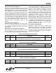
U4D (Modem Control Register 1—MOD1)
U4D is a bit-mapped register that controls various
telephony functions including the enabling of calling and
guard tones and loop current verification prior to dialing.
All bits in this register are read/write except the reserved
bits 15, 13, 9, 6, 2, and 0. These bits must not be written
with a logic 1 and reading them returns a value of 0.
(See Table 43.)
Bit 14 (TOCT) = 0 (default) turns off Calling Tone after
Answer Tone detection and allows Calling Tone
cadence to complete before proceeding with connect
sequence (per V.25). TOCT = 1 turns off Calling Tone
200 ms after Answer Tone detection begins.
Bit 12 (NHFP) = 0 (default) disables hook-flash during
pulse dialing (ignores & and ! dial modifiers). NHFP = 1
enables hook-flash during pulse dialing.
Bit 11 (NHFD) = 0 (default) disables hook-flash during
dial string (tone or pulse). NHFD = 1 enables hook-flash
during (tone or pulse) dial string.
Bit 10 (CLPD) = 0 (default) Modem ignores loop current
prior to dialing. If CLPD = 1, modem measures loop
current prior to dialing. This bit is used in conjunction
with the loop current debounce registers U50 and U51
(LCDN and LCDF), and U4D bit 1 (LLC). U50 provides
a delay between the modem going off-hook and the
loop current measurement. The delay allows the loop
current to stabilize prior to the measurement. Some
countries require the presence of loop current prior to
dialing.
Bit 8 (FTP) = 0 (default) allows mixing tone and pulse
dialing in a single AT command. FTP = 1 forces the first
dialing mode encountered (tone or pulse) for the entire
AT command.
Bit 7 (SPDM) = 0 (default) causes the modem to pulse
dial if an ATDP command is given. If this bit is set to 1
the pulse dial modifier, P, is ignored, and the dial
command is carried out as a tone dial (ATDT).
Bit 5 (GT18) = 0 (default) disables the 1800 Hz Guard
tone. GT18 = 1 enables the 1800 Hz Guard tone.
Bit 4 (GT55) = 0 (default) disables the 550 Hz Guard
tone. GT55 = 1 enables the 550 Hz Guard tone.
Bit 3 (CTE) = 0 (default) disables and CTE = 1 enables
the Calling Tone referred to in bit 14 (TOCT). The
Calling Tone is a 1300 Hz tone in originate mode with a
0.5–0.7 sec on/1.5–2.0 sec off cadence as described in
V.25.
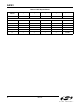
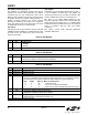
Table 41. DTMF Dial Registers
Register Name Description Default
U46 DTPL DTMF power level 0x09B0
U47 DTNT DTMF on time (ms units). 0x0064
U48 DTFT DTMF off time (ms units). 0x0064
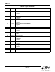
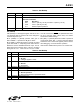
Table 42. Ring Detect Registers
Register Name Description Default
U49 RGFH Ring frequency high (2400/maximum valid ring frequency in Hz). 0x0022
U4A RGFD Ring frequency delta (2400/minimum valid ring frequency in Hz)—
(2400/maximum valid ring frequency in Hz).
0x007A
U4B RGMN Ring cadence minimum ON time in seconds multiplied by 2400. 0x0258
U4C RGNX Ring cadence maximum total time in seconds multiplied by 2400. 0x6720