
Specifications


AN93
Rev. 0.8 85
Reset settings = 0x0000
9RIMRing Indicator Mask.
0 = Change in RI does not affect INT
.
1 = RI low-to-high transition triggers INT
.
8DCDMData Carrier Detect Mask.
0 = Change in DCD (U70, bit 0) does not affect INT
.
1 = DCD high-to-low transition triggers INT
.
7:5 Reserved Read returns zero.
4CIDCaller ID (sticky).
1 = Caller ID preamble detected; data to follow. Clears on :I read.
3OCDOvercurrent Detect (sticky).
1 = Overcurrent condition has occurred. Clears on :I read.
2 PPD Parallel Phone Detect (sticky).
1 = Parallel phone detected since last off-hook event. Clears on :I read.
1RIRing Indicator (sticky).
1 = Ring event has occurred (Si2493/57/34/15/04 on-hook). Clears on :I read.
0DCDData Carrier Detect (status).
1 = carrier detected (inverse of DCD
pin).
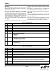
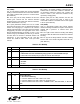
Table 60. U70 Bit Map (Continued)
Bit Name Function
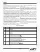
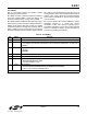
U71 IO1
Bit D15 D14 D13 D12 D11 D10 D9 D8 D7 D6 D5 D4 D3 D2 D1 D0
Name
COMP PRT
Type
R/W R/W
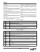
Bit Name Function
15:5 Reserved Read returns zero.
4COMP0 – Disables compression (PCM mode).
1 – Enables linear compression.
3:1 Reserved
0PRT0 – Disables PCM mode.
1 – Enables PCM mode.