
Specifications


Si2457/Si2434/Si2415
26 Rev. 0.91
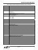
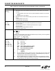
+IFC Options
+IFC = A
+IFC = A,B
Specifies the flow control to be implemented.
A Specifies the flow control method used by the host to control data from the modem
0None
1 Local XON/OFF flow control. Does not pass XON/XOFF character to the remote
modem.
2 Hardware flow control (RTS)
B Specifies the flow control method used by the modem to control data from the host
0 None
1 Local XON/OFF flow control.
2 Hardware flow control (CTS).
+ITF Options
+ITF = A
+ITF = A,B
+ITF = A,B,C
Transmit flow control threshold.
A Threshold above which the modem will generate a flow off signal
<0 to 511> bytes
B Threshold below which the modem will generate a flow on signal
<0 to 511> bytes
C Polling interval for <EM><BNUM> indicator
0 to 300 in 10 msec units.
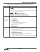
+MR = X
Modulation reporting control.
X
Mode
0 Disabled
1 Enabled
If enabled, the intermediate result code is transmitted at the point during connect negotiation.
The format of this result code is as follows:
+MCR: <carrier> e.g. +MCR: V32B
+MRR: <rate> e.g. +MRR: 14400
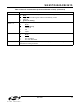
+MS Options
+MS = A
+MS = A,B
+MS = A,B,C
+MS = A,B,C,D
+MS = A,B,C,D,E
+MS = A,B,C,D,E,F
Modulation Selection.
A Preferred modem carrier
V21 ITU-T V.21
V22 ITU-T V.22
V22B ITU-T V.22bis
V32 ITU-T V.32
V32B ITU-T V.32bis (default for Si2415)
V34 ITU-T V.34 (default for Si2434)
V90 ITU-T V.90 (default for Si2457)
B Automatic modulation negotiation
0 Disabled
1 Enabled
C,D Min TX rate/Max TX rate are optional numeric values that specify the lowest value
at which the DCE may establish a connection. If unspecified (set to 0), they are
determined by the carrier and automode settings.
E,F Min RX rate/Max RX rate are optional numeric values which specify the highest
value at which the DCE may establish a connection. If unspecified (set to 0), they
are determined by the carrier and automode settings.
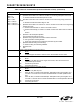
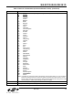
Table 9. Basic AT Command Set (Command Defaults in Bold) (Continued)
Command Action