
Specifications

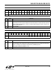

Si2457/Si2434/Si2415
52 Rev. 0.91
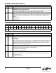
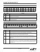
Reset settings = 0x0000
1RZRinger Impedance.
0 = Maximum (high) ringer impedance.
1 = Synthesize ringer impedance. C15, R14, Z2, and Z3 must not be installed when setting this
bit. See the “Ringer Impedance” section in “AN93: Modem Designer’s Guide”.
0RTRinger Threshold Select.
Used to satisfy country requirements on ring detection. Signals below the lower level does not
generate a ring detection; signals above the upper level are guaranteed to generate a ring
detection.
0 = 11 to 22 V
rms
.
1 = 17 to 33 V
rms
.
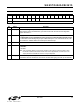
U68 ITC2
Bit D15 D14 D13 D12 D11 D10 D9 D8 D7 D6 D5 D4 D3 D2 D1 D0
Name BTE ROV BTD
Type R/W R/W R/W
Bit Name Function
15:3 Reserved
Do not modify.
2BTEBilling Tone Protect Enable.
0 = Disabled.
1 = Enabled.
When set, the DAA responds automatically to a collapse of the line-derived power supply dur-
ing a billing tone event. When off-hook, if BTE = 1 and BTD goes high, the dc termination is
released (800 Ω presented to line). If BTE and RIM (U70, bit 9) are set, an RI (U70, bit 1)
interrupt also occurs when BTD goes high.
1ROVReceive Overload.
The bit is set when the receive input (i.e., receive pin goes below ground) has an excessive
input level. This bit is cleared by writing a 0 to this location.
0 = Normal receive input level.
1 = Excessive receive input level.
0BTDBilling Tone Detected.
This bit is set if a billing tone is detected. This bit is cleared by writing a 0 to this location.
0 = No billing tone.
1 = Billing tone detected.
Bit Name Function