
Specifications


AN93
Rev. 0.9 139
3.5.20.3. Caller ID
The ISOmodem supports all major caller ID (CID) types.
CID is disabled (+VCID = 0) when the modem is in the
default state. Setting +VCID = 1 via the AT+VCID = 1
command enables decoded CID, while setting
+VCID = 2 causes raw caller ID data to be output. The
specific CID mode is selected by +VCDT, which is set to
the US Bellcore standard by default. The
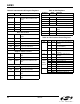
“AT+VCDT = n” command is used to define the CID
mode according to the decimal values of “n” defined in
Table 95. U70[4] (CID) is a sticky bit that is set when a
CID preamble is received and cleared with an AT:I
(“Interrupt read”) command.
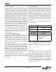
Table 96 shows the AT command string that configures
the ISOmodem for Japan caller ID.
The following sections describe each CID mode.
3.5.20.3.1. US Bellcore Caller ID
The ISOmodem detects the first ring burst, echoes
“RING” to the host, and prepares to detect the CID
preamble. If +VCID = 2, 50 continuous mark bits (1s)
are detected; the “CIDM” response is echoed to the host
(indicating the mark sequence was received and FSK
modulated CID data will follow), and INT
is triggered if
enabled.
Next the CID algorithm looks for the start bit, assembles
the characters, and sends them to the host as they are
received. When the CID burst is finished, the carrier is
lost, and “NO CARRIER” is echoed to the host. The
ISOmodem continues to detect subsequent ring bursts,
echoes “RING” to the host, increments the ring counter,
S1, and automatically answers after the number of rings
specified in S0.
3.5.20.3.2. Forced Caller ID
In this mode, the ISOmodem continuously monitors TIP
and RING while on-hook for the CID mark sequence
and FSK data. This mode is useful in systems requiring
detection of CID data before the ring burst. It is also
useful for detecting voice mail indicator signals and for
supporting Type II Caller ID.
3.5.20.3.3. UK Caller ID
The ISOmodem first detects a line polarity reversal,
echoes “FLASH” to the host, and triggers the INT pin.
The ISOmodem then searches for the Idle State Tone
Alert signal and, when detected, echoes “STAS” to the
host. After the Idle State Tone Alert Signal is completed,
the ISOmodem goes off-hook then on-hook to apply the
15 ms wetting pulse to the local loop. Next, the
ISOmodem prepares to detect the CID preamble. After
50 continuous mark bits (1s) are detected, the “CIDM”
response is echoed to the host indicating that the mark
sequence was received and that FSK-modulated CID
data will follow, and INT
is again triggered. Then, the
CID algorithm looks for the start bit, assembles the
characters, and sends them to the host as they are
received. When the CID burst is finished, the carrier is
lost, and “NO CARRIER” is echoed to the host. The
ISOmodem detects ring bursts, echos “RING” to the
host, increments the ring counter, S1, and automatically
answers after the number of rings specified in S0.
3.5.20.3.4. Japan Caller ID
The ISOmodem detects a line polarity reversal and a
brief ring burst, then goes off-hook and triggers the INT
pin. CID data is sent using the V.23 specification. After
detecting 40 mark bits (1s), the ISOmodem searches for
a start-bit. “CIDM” is echoed to the host when a start bit
is received. The modem then starts to assemble
characters and sends them to the host. When the CID
signal is lost, the ISOmodem hangs up and echoes “NO
CARRIER” to the host. The modem then waits for the
normal ring signal.
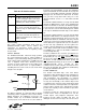
Table 95. Caller ID Modes
n +VCDT Settings
0 After ring only (US Bellcore) default
1 Force CID monitor (always on)
2UK
3 Japan
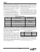
Table 96. Japan Caller ID
Command Function
AT+VCID = 1 Enables caller ID.
AT+VCDT = 3 Selects Japan CID mode.