
Specifications


AN93
Rev. 0.9 17
include a costly LC filter internal to the modem when it
may only be necessary to support a few countries/
customers.
Alternatively, when a billing tone is detected, the host
software may notify the user that a billing tone has
occurred. This notification can be used to prompt the
user to contact the telephone company and have the
billing tones disabled or to purchase an external LC filter.
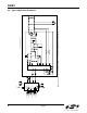
2.2.16. Billing Tone Filter (Optional)
To operate without degradation during billing tones in
Germany, Switzerland, and South Africa, an external LC
notch filter is required. (The Si3018/10 can remain off-
hook during a billing tone event, but modem data is lost
[or a modem disconnect or retrain may occur] in the
presence of large billing tone signals.) The notch filter
design requires two notches: one at 12 kHz and one at
16 kHz. Because these components are expensive and
few countries supply billing tone support, this filter is
typically placed in an external dongle or added as a
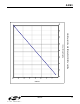
population option for these countries. Figure 7 shows an
example billing tone filter.
L3 must carry the entire loop current. The series
resistance of the inductors is important to achieve a
narrow and deep notch. This design has more than
25 dB of attenuation at 12 and 16 kHz.
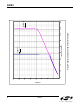
Figure 7. Billing Tone Filter
The billing tone filter affects the ac termination and
return loss. The global complex ac termination passes
worldwide return loss specifications with and without the
billing tone filter by at least 3 dB.
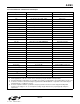
2.2.17. PCM Interface (24-Pin TSSOP Only)
Table 7 lists the pin connections for the Si2493/57/34/
15/04 PCM interface. This interface enables Voice
Mode operation. See "3.5. Programming Examples" on
page 105 for additional information.
L4
C3
RING
TIP
FROM
LINE
To
DAA
C1
C2
L3
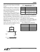
Table 6. Optional Billing Tone Filters
Component Values
Symbol Value
C1,C2 0.027 µF, 50 V, ±10%
C3 0.01 µF, 250 V, ±10%
L3 3.3 mH, >120 mA, <10 Ω, ±10%
Coilcraft RFB0810-332 or equivalent
L4 10 mH, >40 mA, <10 Ω, ±10%
Coilcraft RFB0810-103 or equivalent
Table 7. PCM Interface Pin Connection
Si24XX Pin Si24XX Signal
3CLKOUT
4 FSYNC
24 SDO
18 SDI
12 RESET*