
Specifications

AN93
188 Rev. 0.9
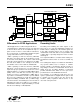
In the end, the only thing that matters in an EPOS application is the ability to send and receive HDLC frames
across the DTE. For this, the ability of the host to tell the modem "end of transmit frame" and the ability for the
modem to tell the host "crc check successful" is, in essence, the kernel of V.80 use in an EPOS application.
One final note before showing an example… the V.80 standard refers to a "Transparent Sub-Mode" and a "Framed
Sub-Mode". The main idea behind the Transparent Sub-Mode is to allow the host to specifically decide what bits
are being sent across the DCE. In the Transparent Sub-Mode, nothing is left out, and the host is responsible for
every single bit that is transmitted to and from the modem. In the Framed Sub-mode, the HDLC handling is
performed by the modem, and, therefore, there are actions taken by the modem that the host assumes and does
not worry about. In EPOS applications, only the "Framed Sub-Mode" is of any importance.
Example: Let's take an example of sending an HDLC Frame containing the following bytes:
0xFF 0x11
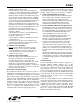
The host will transmit the following byte stream. Note that the 0x11 is sent as an <EM><t3> or 0x19 0xA0. An
<EM><flag> or 0x19 0xB1 denotes the end of frame.
0xFF 0x19 0xA0 0x19 0xB1
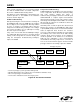
At the UART interface at TXD, the bit-representation is:
strt 0xFF stp stp 0x19 stp strt 0xA0 stp strt 0x19 stp strt 0xB1
1 0 11111111 1 0 10001001 1 0 00000101 1 0 10001001 1 0 10001101
The modem strips off the start and stop bits and reconstructs the original bytes:
0xFF 0x19 0xA0 0x19 0xB1
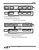
The transparency characters are resolved, and, since the <EM><flag> is present, the Frame Check Sequence is
calculated. Let us assume that the FCS is 0xC00F:
16-bit FCS
0xFF 0x11 0xC0 0x0F
Adding the HDLC flags and zero-stuffing, the bit stream is shown as follows. Note that the bit stream containing the
0xFF and 0x0F bytes have inserted zero bits. The algorithm is fairly simple in that whenever there are five ones in
a row, a bit is inserted. The inserted bits are shown in red. This bit stream is then modulated and transmitted out to
the DCE.
16-bit FCS
Flag 0xFF 0x11 0xC0 0x0F Flag
01111110 111110111 10001000 00000011 111010000 01111110
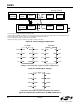
The receive process reverses the above steps. The receiver hunts for HDLC flags and synchronizes to the HDLC
flag stream. It then extracts the frame between the HDLC Flags and performs zero-bit deletion on the payload. The
receiver also calculates the CRC and matches with the 16-bit FCS of the frame. Then, the <EM> transparency is
added, and finally, the <EM><flag> is sent as an indication that the calculated CRC of the frame matches the FCS.