
Specifications

AN93
Rev. 0.9 21
3. Software Design Reference
This section provides information about the architecture
of the modem, functional blocks, registers, and their
interaction. The AT command set is presented, and
options are explained. The accessible memory
locations (S-Registers and U-Registers) and optional
external EEPROM are described. Instructions for writing
to and reading from them are discussed along with any
limitations or special considerations. A large number of
configuration and programming examples are offered as
illustrations of actual testable applications. These
examples can be used alone or in combination to create
the desired modem operation.
This section is organized into five major sections: "3.1.
Controller", "3.2. DSP" on page 58, "3.3. Memory" on
page 58, "3.4. Digital Interface" on page 98, and "3.5.
Programming Examples" on page 105. The “Controller”
section contains information about using controller
functions and features, such as the AT command set,
result codes, escape methods, power control, and
system reset information. The “DSP” section is brief
because the programmer has little control over the
operation of the DSP. The use of features that modify
DSP behavior is described in other sections. The
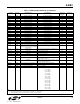
“Memory” section describes the use of S-Registers and
U-Registers to control the operation, features, and
configuration of the modem. The optional external SPI
EEPROM is useful for the non-volatile storage of
configuration settings, such as firmware upgrades or
country setup commands. The “Digital Interface” section
describes the serial interface and parallel interface.
Finally, the “Programming Examples” section illustrates
the implementation of modem functions and features
with the required AT commands and register values.
Configuration data is provided for most countries. These
examples can be used both to test modem operation
and as a programming aid.
The Si2493/57/34/15/04 modem chipset family is
controller-based. No modem drivers are required to run
on the system processor. This makes the Si2493/57/34/
15/04 modem family ideal for embedded systems
because a wide variety of processors and operating
systems can interface with the Si2493/57/34/15/04
through a simple UART (universal asynchronous
receiver transmitter) driver.
The modems in this family operate at maximum connect
rates of 48 kbps upstream/V.92 (Si2493), 56 kbps
downstream/V.90 (Si2457), 33.6 kbps/V.34 (Si2434),
14.4 kbps/V.32b (Si2415), and 2400 bps/ V.22b
(Si2404) and support all standard ITU-T fall-back
modes. These chipsets can be programmed to comply
with FCC, JATE, CTR21, and other country-specific
PTT requirements. They also support V.42 and MNP2–4
error correction and V.42b and MNP5 compression. A
“fast connect” and “transparent HDLC” are also
supported.
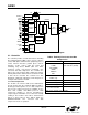
The Si2493/57/34/15/04 is highly integrated. The basic
Si2493/57/34/15/04 functional blocks are shown in
Figure 9. The Si2493/57/34/15/04 includes a controller,
data pump (DSP), ROM, RAM, an oscillator, phase-
locked loop (PLL), timer, serial interface, UART, a
parallel interface option, and a DAA interface. The
modem software is permanently stored in the on-chip
ROM. Only modem setup information (other than
defaults) and other software updates must be stored on
the host or optional external EEPROM and downloaded
to the on-chip RAM during initialization. There is no non-
volatile on-chip memory other than Program ROM. The
default user interface for the Si2493/57/34/15/04 is the
serial interface including the UART.