
Specifications

AN93
Rev. 0.9 23
3.1.2. Error Correction
The Si2493/57/34/15/04 ISOmodem can employ error
correction (reliable) protocols to ensure error-free
delivery of data sent between two modems. The error
control methods are based on grouping data into frames
with checksums determined by the contents of each
frame. The receiving modem checks the frames and
sends acknowledgments to the transmitting modem.
When it detects a faulty frame, the receiving modem
requests a retransmission. Frame length varies
according to the amount of data transmitted or the
number of retransmissions requested from the opposite
end.
The Si2493/57/34/15/04 supports V.42 and MNP2–4
error correction protocols. V.42 (LAPM) is most
commonly used and is enabled in \N3 and \N4 modes.
In the default mode (\N3), the Si2493/57/34/15/04
attempts to connect with V.42 error correction and
V.42bis data compression (Si2457/34/15) and falls back
to either V.42 only, MNP 2–5, or no error correction
(wire mode) if necessary. In \N4 mode, the Si2493/57/
34/15/04 hangs up if a V.42 connection cannot be
established. If the ISOmodem hangs up in V.42 mode
after all data is successfully sent, the result code is
“OK”. If the modem hangs up before all data is
successfully sent, the result code is “No Carrier”. If the
modem connects without a protocol, “No Carrier” is
always sent.
The V.42 specification allows an alternate error
correction protocol, MNP2-4. MNP2-4 is enabled in \N2
mode. In \N2 mode, the Si2493/57/34/15/04 hangs up if
an MNP2, 3, or 4 connection cannot be established.
3.1.3. Wire Mode
Wire mode (\N0) is used to communicate with standard,
non-error-correcting modems. When optioned with \N3,
the Si2493/57/34/15/04 falls back to Wire mode if it fails
in an attempt to negotiate a V.42 or MNP2-4 link with the
remote modem. Error correction and data compression
are not active in Wire mode.
3.1.4. Fast Connect
The Si2493/57/34/15/04 supports several fast connect
modes of operation to reduce the time of a connect
sequence in originate mode.
3.1.5. V.29 Fast Connect
In addition to the low modulation speed fast connect
modes, the modem (only Si2493/57/34/15) also
supports a fast connect mode based on the 9600 bps
V.29 fax modulation standard. V.29 Fast Connect is
available as a patch for Rev C or greater. Please
contact Silicon Laboratories for additional details.
3.1.6. Legacy Synchronous DCE Mode/V.80
Synchronous Access Mode
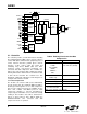
The Si2493/57/34/15/04 supports two different DTE
interfaces to implement an Asynchronous DTE to
Synchronous DCE conversion.
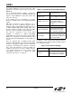
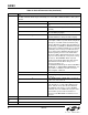
Table 10 provides high-level options to choose between
the Legacy Synchronous DCE Mode and the newer
V.80 synchronous access mode.
The synchronous access mode has more features than
the Legacy Synchronous DCE Mode. For new designs,
use the newer synchronous access mode interface.
Otherwise, if there is existing software written with the
Legacy Synchronous DCE Mode interface, no software
changes are required as long as the AT+ES command
settings are not changed from the default value.
3.1.7. V.80 Mode
As shown in Table 11, the synchronous access mode is
chosen by using the AT+ES=6,,8 command setting.
When using the synchronous access mode, it is
expected that the AT\N0 command be used to disable
all other error correction protocols that may interfere
with V.80 synchronous access mode operation.
The V.80 Mode has two distinct submodes. Switching
between these two submodes can be accomplished
within the confines of the same connection through the
use of In-Band commands.
Transparent Submode
Framed Submode
The Transparent Submode creates a direct bit-by-bit
translation from the DTE to and from the DCE. Any
application that requires a method of reconstructing a
serial bit-stream at the DCE can use the Transparent
Sub-mode.
The Framed Sub-mode represents data at the DCE in
HDLC/SDLC frames. This submode is typically used in
Point-of-Sale Terminal Applications. A common feature
used in conjunction with the Framed Submode is the
use of the 16-bit CRC. When used with the CRC option,
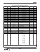
Table 10. Synchronous Mode Overview
Mode U-Register AT+ES
Settings
Neither U7A[2] = 0 +ES = D,,D
Legacy Synchronous
DCE Mode
U7A[2] = 1 +ES = D,,D
Synchronous Access
Mode
+ES = 6,,8