
Specifications


AN93
88 Rev. 0.9
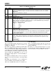
3.3.33. U68 (ITC2)
U68 is a bit-mapped register with bits 15:3 reserved.
Reading these bits returns zero. Bits 4 and 2:0 are all
read/write (see Table 55).
Bit 2 (BTE) = 0
b
(default) is disabled by default. When
BTE = 1
b
, the DAA automatically responds to a collapse
of the line-derived power supply during a billing tone
event. When off-hook, if BTE = 1
b
and BTD goes high,
the dc termination is increased to 800 Ω to reduce loop
current. If BTE and U70[9] (RIM) are set to 1
b
, an
interrupt from U70[1] (RI) also occurs when BTD goes
to 1
b
(high).
Bit 1 (ROV) is normally 0
b
and is set to 1
b
to report an
excessive receive input level. ROV is cleared by writing
it to 0
b
.
Bit 0 (BTD) = 0
b
normally but is set to 1 if a billing tone
is detected. BTD is cleared by writing a 0
b
to BTD.
U68 resets to 0x0000 with a power-on or manual reset.
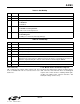
3.3.34. U6A (ITC4)
U6A is a bit-mapped register with bits 15:3 and 1:0
reserved. Reading these bits returns zero. Bit 2 is read-
only. (See Table 56.)
Bit 2 (OVL) is a read-only bit that detects a receive
overload. This bit is similar to U68[1] (ROV) except OVL
clears itself after the overload condition is removed.
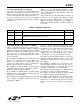
7 DCR DC Impedance Selection.
0=50Ω dc termination slope is selected. This mode should be used for all standard
applications.
1=800Ω dc termination is selected.
6OHSOn-Hook Speed.
See OHS2.
5:4 Reserved Read returns zero.
3:2 DCV[1:0] TIP/RING Voltage Adjust.
These bits adjust the voltage on the DCT pin of the line-side device, which affects the TIP/RING
voltage on the line. Low-voltage countries should use a lower TIP/RING voltage. Raising the
TIP/RING voltage can improve signal headroom.
DCV[1:0] DCT Pin Voltage
00 3.1 V
01 3.2 V
10 3.35 V
11 3.5 V
1RZRinger Impedance.
0 = Maximum (high) ringer impedance.
1 = Synthesize ringer impedance. C15, R14, Z2, and Z3 must not be installed when setting this
bit. See the “Ringer Impedance” section in “AN93: Si2493/Si2457/Si2434/Si2415/Si2404
Modem Designer’s Guide”.
0RTRinger Threshold Select.
Used to satisfy country requirements on ring detection. Signals below the lower level do not
generate a ring detection; signals above the upper level are guaranteed to generate a ring
detection.
0 = 11 to 22 V
rms
.
1 = 17 to 33 V
rms
.
Table 54. U67 Bit Map (Continued)
Bit Name Function