AN93 Si2493/57/34/15/04 (Revision D) and Si2494/39 Modem Designer ’s Guide 1. Introduction The Si2494/93/57/39/34/15/04 ISOmodem chipset family consists of a 38-pin QFN (Si2494/39) or 24-pin TSSOP (Si2493/57/34/15/04) or 16-pin SOIC (Si2493/57/34/15/04) low-voltage modem device, and a 16-pin SOIC lineside DAA device (Si3018/10) connecting directly with the telephone local loop (Tip and Ring).
AN93 2 Rev. 1.
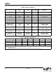
AN93 TABLE O F C ONTENTS Section Page 1. Introduction . . . . . . . . . . . . . . . . . . . . . . . . . . . . . . . . . . . . . . . . . . . . . . . . . . . . . . . . . . . . . . 1 1.1. Selection Guide . . . . . . . . . . . . . . . . . . . . . . . . . . . . . . . . . . . . . . . . . . . . . . . . . . . . . . 9 2. Modem (System-Side) Device . . . . . . . . . . . . . . . . . . . . . . . . . . . . . . . . . . . . . . . . . . . . . . . 11 2.1. Resetting the Device . . . . . . . . . . . . . . . . . . . . . . .
AN93 2.6.6.2. AT Command Macro Example . . . . . . . . . . . . . . . . . . . . . . . . . . . . . . . . . 35 2.6.6.3. Autoloading Firmware Upgrade Example . . . . . . . . . . . . . . . . . . . . . . . . 35 2.6.6.4. Combination Example . . . . . . . . . . . . . . . . . . . . . . . . . . . . . . . . . . . . . . . 36 3. DAA (Line-Side) Device . . . . . . . . . . . . . . . . . . . . . . . . . . . . . . . . . . . . . . . . . . . . . . . . . . . . 38 3.1. Hookswitch and DC Termination . . . . . . . . . . . . . . .
AN93 5.7.11. U4F (Flash Hook Time Register) . . . . . . . . . . . . . . . . . . . . . . . . . . . . . . . . . 105 5.7.12. U50–U51 (Loop Current Debouncing Registers) . . . . . . . . . . . . . . . . . . . . . 105 5.7.13. U52 (Transmit Level Register) . . . . . . . . . . . . . . . . . . . . . . . . . . . . . . . . . . . 105 5.7.14. U53 (Modem Control Register 2) . . . . . . . . . . . . . . . . . . . . . . . . . . . . . . . . . 106 5.7.15. U54 (Calibration Timing Register) . . . . . . . . . . . . . . . . . . .
AN93 6.6. Intrusion/Parallel Phone Detection . . . . . . . . . . . . . . . . . . . . . . . . . . . . . . . . . . . . . . 161 6.6.1. On-Hook Condition . . . . . . . . . . . . . . . . . . . . . . . . . . . . . . . . . . . . . . . . . . . . . 161 6.6.1.1. Line Not Present/In Use Indication (Method 1—Fixed) . . . . . . . . . . . . . 161 6.6.1.2. Line Not Present/In Use Indication (Method 2—Adaptive). . . . . . . . . . . 162 6.6.2. Off-Hook Condition . . . . . . . . . . . . . . . . . . . . . . . . . . . . . . .
AN93 7.5.8. Speakerphone Transition . . . . . . . . . . . . . . . . . . . . . . . . . . . . . . . . . . . . . . . . 200 7.6. Telephone Answering Machine . . . . . . . . . . . . . . . . . . . . . . . . . . . . . . . . . . . . . . . . 201 7.6.1. Overview. . . . . . . . . . . . . . . . . . . . . . . . . . . . . . . . . . . . . . . . . . . . . . . . . . . . . 201 7.6.2. TAM Hands-Free—Idle. . . . . . . . . . . . . . . . . . . . . . . . . . . . . . . . . . . . . . . . . . 201 7.6.2.1. Record OGM . . . . . . . .
AN93 9. Chinese ePOS SMS . . . . . . . . . . . . . . . . . . . . . . . . . . . . . . . . . . . . . . . . . . . . . . . . . . . . . . 234 9.1. Introduction . . . . . . . . . . . . . . . . . . . . . . . . . . . . . . . . . . . . . . . . . . . . . . . . . . . . . . . . 234 9.2. SMS AT Command Set . . . . . . . . . . . . . . . . . . . . . . . . . . . . . . . . . . . . . . . . . . . . . . 235 9.2.1. SMS User Registers . . . . . . . . . . . . . . . . . . . . . . . . . . . . . . . . . . . . . . . . . . . . 236 9.
AN93 1.1. Selection Guide Tables 1 through 3 list the modulations, protocols, carriers, tones and interface modes supported by the Si2494/39 and Si2493/57/34/15/04 ISOmodem family. The Si2493 supports all modulations and protocols from Bell 103 through V.92. The Si2457 supports all modulations and protocols from Bell 103 through V.90. The Si2434 supports all modulations and protocols from Bell 103 through V.34. The Si2415 supports all modulations and protocols from Bell 103 through V.32bis.
AN93 Table 3. Carriers and Tones Specification Transmit Carrier (Hz) Receive Carrier (Hz) Answer Tone (Hz) Carrier Detect (Acquire/ Release) V.92 Variable Variable per ITU-T V.92 V.90 Variable Variable per ITU-T V.90 V.34 Variable Variable per ITU-T V.34 V.32bis 1800 1800 2100 per ITU-T V.32bis V.32 1800 1800 2100 per ITU-T V.32 V.29 1700 1700 V.22bis, V.22 Originate/answer 1200 2400 2400 1200 2100 –43 dBm/–48 dBm –43 dBm/–48 dBm V.
AN93 2. Modem (System-Side) Device The Si24xx ISOmodem system-side devices contain a controller, a DSP, program memory (ROM), data memory (RAM), UART, SPI and parallel interfaces, a crystal oscillator, and an isolation capacitor interface. The following sections describe the reset sequence, the host interface, the isolation interface, low-power modes, SSI/voice mode and the EEPROM interface. 2.1.
AN93 6. Set non-default frequency values—Ring. 7. Set non-default filter parameters. 8. Set non-default S-register values. The modem is now ready to detect rings, answer another modem, call, or dial out to a remote modem. Some key default settings for the modem after reset or powerup include the following: V.92 and fall-backs enabled (Si2494/93) V.90 and fall-backs enabled (Si2457) V.34 and fall-backs enabled (Si2439/34) V.32bis and fall-backs enabled (Si2415) V.
AN93 2.1.3. Reset-Strap Options for 16-Pin SOIC Package The clock frequency and interface on the 16-pin SOIC package are selected according to Table 5 below. The parallel interface, EEPROM and autobaud options are not available in the 16-pin SOIC package. Table 5. SOIC-16 Reset-Strap Options Mode Reset-Strap Pins Interface Input Clock Pin 3 RI Pin 5, RXD/MISO Pin 7, CTS/SCLK Pin 11 INT Pin 15 DCD UART 32 kHz 0 X 1 1 X 4.
AN93 2.1.4.1. Reset Strapping Options for TSSOP-24 with UART-Interface UART-interface options for the 24-pin TSSOP package are shown in Table 6 below. Table 6. TSSOP-24 UART-Interface Options Mode Reset-Strap Pins Input Clock Autobaud Disabled? Three-Wire EEPROM Interface? Pin 4 FSYNC 32 kHz No No 1 Yes Yes 4.
AN93 2.1.4.3. Reset Strapping Options for TSSOP with SPI-Interface Table 8 lists the SPI-interface options for the 24-pin TSSOP package. Table 8. TSSOP-24 SPI-Interface Clock-Frequency Options Mode Reset-Strap Pins Input Clock Three-Wire EEPROM Interface? Pin 4 FSYNC 32 kHz No 1 Yes 4.9152 MHz 27 MHz Pin 9, RXD Pin 11, SCLK Pin 15, AOUT Pin 18, SDI/EESD Pin 16 INT Pin 17 RI Pin 23 DCD 1 0 1 1 0 1 0 1 1 No 1 1 0 0 X Yes 0 1 0 0 X No 1 1 0 1 0 Yes 0 1 0 1 0 2.1.
AN93 2.1.5.2. Reset Strapping Options for QFN Parts with SPI Operation Table 10 lists the reset strapping options for QFN parts with SPI operation. Table 10. Reset Strapping Options for QFN parts with SPI Operation Input Clk Three-Wire EEPROM Interface 32 kHz 4.
AN93 2.2. System Interface The ISOmodem can be connected to a host processor through a UART, SPI or parallel interface. Connection to the chip requires low-voltage CMOS signal levels from the host and any other circuitry interfacing directly. The following sections describe the digital interface options in detail. 2.2.1. Interface Selection The interface is selected during reset, as described in "2.1. Resetting the Device".
AN93 Table 14. Pin Functions vs. Interface Mode (QFN-38) 18 Pin # UART Mode SPI Mode Parallel Mode 35 INT INT INT 34 GPIO18 GPIO18 D0 33 GPIO17 GPIO17 D1 32 GPIO16 GPIO16 D2 31 GPIO23 GPIO23 D3 30 GPIO24 GPIO24 D4 29 ESC D5 28 DCD D6 24 RTS SS D7 23 TXD MOSI WR 22 RXD MISO RD 21 CTS SCLK CS 20 GPIO11 GPIO11 A0 19 RI Rev. 1.
AN93 2.2.2. Interface Signal Description The following tables describe each set of UART, parallel and SPI interface signals: Table 15. UART-Interface Signals Signal Direction Description TXD Input Data input from host TXD pin RXD Output Data output to host RXD pin RTS Input CTS Output Active-low request-to-send input for flow control Clear to send: Si2493 is ready to receive data on the TXD pin (active low) Table 16.
AN93 The UART interface synchronizes on the start bits of incoming characters and samples the data bit field and stop bits. The interface is designed to accommodate character lengths of 8, 9, 10, and 11 bits giving data fields of 6, 7, 8, or 9 bits. Data width can be set to 6, 7, or 8 bits with the AT\Bn command. Parity can be set to odd, even, mark, or space by the AT\Pn command in conjunction with AT\B2 or AT\B5. Other AT\Bn settings have no parity. Table 18.
AN93 : Table 19. Serial Formats Detected in Autobaud Mode Symbol Data bits Parity Stop bits 7N1 7 None (mark) 1 7N2 7 None (mark) 2 7S1 7 None (space) 1 7O1 7 Odd 1 7E1 7 Even 1 8N1 8 None (mark) 1 8E1 8 Even 1 8O1 8 Odd 1 9N1 9 None (mark) 1 Note: For 7N1, the modem is programmed to 7 data bits, mark parity and one stop bit. This may be changed with the AT\P and AT\B commands.
AN93 Table 20. Register U70 Signals INT Can Monitor Signal U70 Bit Function DCD 0 Data Carrier Detect—active high (inverse of DCD pin) RI 1 Ring Indicator—active high (inverse of RI pin) PPD 2 Parallel Phone Detect OCD 3 Overcurrent Detect CID 4 Caller ID Preamble Detect 1024 Character Elastic Tx Buffer SRAM CTS CTS Deasserts 796 Characters Tx Data 14-Character Hardware Buffer Transmit 128 Characters CTS Asserts Figure 3.
AN93 A block diagram of the UART in the serial interface mode is shown in Figure 5. . 11 Bits to Data Bus MUX RX FIFO TX FIFO TX Shift Register TXD (10) CONTROL CTS (11) RTS (8) RX Shift Register INT (16) RXD (9) Figure 5. UART Serial Interface 2.2.4. Parallel and SPI Interface Operation Refer to "2.1. Resetting the Device" on page 11 for interface selection. The parallel interface has an 8-bit data bus and a single address bit.
AN93 11 Bits to Data Bus MUX TX FIFO 14 Characters RX FIFO 12 Characters Shared-Serial/Parallel CONTROL MUX A0 (3) D0 (16) D1 (17) D2 (18) D3 (22) D4 (23) D5 (24) D6 (4) D7 (8) Parallel Interface Unique Figure 6. Parallel Interface 24 Rev. 1.
AN93 Table 21. Hardware Interface Register Bit Map A0 RD WR Action Register 0 0 1 Read HIR0 0 1 0 Write 1 0 1 Read 1 1 0 Write D7 D6 D5 D4 D3 D2 D1 D0 Modem data or command from receive FIFO Modem data or command to transmit FIFO HIR1 RXF TXE REM INTM INT ESC RTS CTS RXF TXE *Note INTM *Note ESC RTS n/a *Note: REM and INT are read-only bits. 2.2.4.1.
AN93 Bit 6 (TXE) is a read/write bit that gives the status of the 14-byte deep transmit FIFO. If TXE = 0, the transmit FIFO contains three or more bytes. If TXE = 1, the transmit FIFO contains two or fewer bytes. Writing TXE = 0 clears the interrupt but does not change the state of TXE. Bit 5 (REM) is a read-only bit that indicates when the receive FIFO is empty. If REM = 0, the receive FIFO contains valid data. If REM = 1, the receive FIFO is empty.
AN93 Figure 7. Parallel Interface Read Timing Figure 8. Parallel Interface Write Timing Rev. 1.
AN93 2.2.4.4. SPI Interface Operation SPI interface operation is supported in the Si2493/57/34/15/04 Revision D or later and the Si2494/39 Revision A or later. When the device is powered up for SPI interface, the modem becomes an SPI slave, and the pins are configured to SS (chip select input, active low), MOSI (serial data input to modem), MISO (serial data output from modem) and SCLK (serial data clock input). The HIR0 and HIR1 registers described above are also available in SPI mode.
AN93 2.3. Isolation Capacitor Interface The isolation capacitor is a proprietary high-speed interface connecting the modem chip and the DAA chip through a high-voltage isolation barrier provided by two capacitors. It serves three purposes. First, it transfers control signals and transmit data from the modem chip to the DAA chip. Second, it transfers receive and status data from the DAA chip to the modem chip.
AN93 2.5. SSI/Voice Mode (24-Pin TSSOP and 38-Pin QFN Only) Voice mode is supported in the Si2439 and the Si2494. Table 25 lists the pin connections for the ISOmodem SSI interface. This interface enables Voice Mode operation. See "7. Handset, TAM, and Speakerphone Operation" on page 173 for additional information. Table 25.
AN93 2.6. EEPROM Interface (24-Pin TSSOP and 38-Pin QFN Only) The 24-pin TSSOP and 38-pin QFN packages feature an optional three-wire interface (EESD, EECS and EECLK) that may be directly connected to SPI EEPROMs. An EEPROM may contain custom default settings, firmware upgrades, and/or user-defined AT command macros for use in custom AT commands or country codes. Firmware upgrades may also be automatically loaded into the ISOmodem using the BOOT format. 2.6.1.
AN93 Table 28. EEPROM Timing Parameter Symbol Min. Typ. Max. Unit EESD tristated before last falling EECLK edge during read cycle. Last positive half of EECLK cycle is extended to provide both 500 ns minimum EOH and 100 ns EESD before EECLK falling edge.
AN93 2.6.2. Three-Wire SPI Interface to EEPROM To enable the 3-wire SPI interface to EEPROM on the 24-pin TSSOP package, appropriate pins must be reset strapped according to Table 6 on page 14, or Table 8 on page 15, depending on the interface selected. The EEPROM option is not available on the 24-pin TSSOP package if the parallel host interface is selected. Figure 12 shows the connection diagram for the 3-wire SPI interface to EEPROM.
AN93 The commands end with a , which, in combination with the final, provides the delimiter. Boot commands must be the first entry in the EEPROM and are used to set the modem up with custom defaults, such as settings for specific countries, auto answer, or other special settings upon power up or after a hardware or software reset.
AN93 2.6.6.2. AT Command Macro Example This example creates the AT command macro ATN to configure the ISOmodem for operation in Norway. The AT commands required to do this manually are: AT:U2C,00B0,0080 AT:U67,000C,0010,0004 AT:U4D,001 To implement this as an AT command macro, the EEPROM contents should be: N AT:U2C,00B0,0080 AT:U67,000C,0010,0004 AT:U4D,001 This must be written to the EEPROM as ASCII hexadecimal in eight address blocks.
AN93 2.6.6.4. Combination Example This example shows boot commands and custom AT commands stored in the same EEPROM. Table 29.
AN93 Table 30.
AN93 3. DAA (Line-Side) Device The Si3018/10 DAA or line-side device, contains an ADC, a DAC, control circuitry, and an isolation capacitor interface. The Si3018/10 and surrounding circuitry provide all functionality for telephone line interface requirement compliance, including a full-wave rectifier bridge, hookswitch, dc termination, ac termination, ring detection, loop voltage and current monitoring, and call-progress monitoring.
AN93 3.2. AC Termination The ISOmodem has four ac termination impedances when used with the Si3018 line-side device, selected by the ACT bits in Register U63. The four available settings for the Si3018 are listed in Table 31. If an ACT[3:0] setting other than the four listed in Table 31 is selected, the ac termination is forced to 600 (ACT[3:0] = 0000). Table 31.
AN93 Bit 15 represents the polarity of the Tip-Ring voltage, and a reversal of this bit represents a Tip-Ring polarity reversal. LVS = 0x0000 if the Tip-Ring voltage is less than 3.0 V and, in the on-hook state, can be taken as “no line connected.” The ISOmodem reports the on-hook line voltage with the LVS bits in two’s complement. LVS has a full scale of 87 V with an LSB of 1 V. The first code step (going from 0 to 1) is offset so that a 0 indicates a line voltage of less than 3 V.
AN93 256 ILIM = 1 224 ILIM = 0 192 LCS Bits 160 128 96 64 32 0 0 16 32 48 64 80 Loop Curre nt (m A) 96 112 128 144 Figure 16. Typical Loop Current LCS Transfer Function Table 32. Loop Current Transfer Function LVCS[4:0] Condition 00000 Insufficient line current for normal operation. 00001 Minimum line current for normal operation. 11111 Loop current overload. Overload is defined as 128 mA or more, except in TBR21, where overload is defined as 56 mA or more. Rev. 1.
AN93 3.6. Legacy-Mode Line Voltage and Loop Current Measurement The 5-bit LVCS register, U79 (LVCS) [4:0], reports line voltage measurements when on-hook and loop current measurements when off-hook. Using the LVCS bits, the user can determine the following: When on-hook, detect if a line is connected. When on-hook, detect if a parallel phone is off-hook. When off-hook, detect if a parallel phone goes on or off-hook. Detect if enough loop current is available to operate. 3.7.
AN93 4. Hardware Design Reference This section describes hardware design requirements for optimum Si24xx ISOmodem chipset implementation. There are three important considerations for any hardware design. First, the reference design and components listed in the associated bill of materials should be followed exactly. These designs reflect field experience with millions of deployed units throughout the world and are optimized for cost and performance.
AN93 The second mode is a 32.768 kHz fundamental mode parallel-resonant crystal. Typical crystals require a 12.5 pF load capacitance. This load is calculated as the series combination of the capacitance from each crystal terminal to ground, including parasitic capacitance due to package pins and PCB traces. The parasitic capacitance is estimated as 7 pF per terminal. This, in combination with the 18 pF capacitors, provides 25 pF per terminal, which, in series, yields the proper 12.5 pF load for the crystal.
AN93 C1 C2 L3 TIP FROM LINE L4 To DAA C3 RING Figure 17. Billing-Tone Filter Table 33. Optional Billing Tone Filters Component Values Symbol Value C1,C2 0.027 µF, 50 V, ±10% C3 0.01 µF, 250 V, ±10% L3 3.3 mH, >120 mA, <10 , ±10% Coilcraft RFB0810-332 or equivalent L4 10 mH, >40 mA, <10 , ±10% Coilcraft RFB0810-103 or equivalent Rev. 1.
RESET_ RTS_/D7 RXD/RD_ TXD/WR_ CTS_/CS_/ALE_ CLKOUT/A0/EECS INT_/D0 RI_/D1 EESD/D2 EECLK/D5/RXCLK DCD_/D4 ESC/D3 AOUT/INT_ alt_RI_/D6/TXCLK 12 8 9 10 11 3 16 17 18 24 23 22 15 4 5 21 RESET RTS/D7 RXD/RD TXD/WR CTS/CS/ALE CLKOUT/A0/EECS 13 14 2 1 C51 C53 Y1 R13 R12 C41 C40 R9 C5 Bias Rev. 1.
RESET_ RTS_/D7 RXD/RD_ TXD/WR_ CTS_/CS_/ALE_ CLKOUT/A0/EECS INT_/D0 RI_/D1 EESD/D2 EECLK/D5/RXCLK DCD_/D4 ESC/D3 AOUT/INT_ alt_RI_/D6/TXCLK 12 8 9 10 11 3 16 17 18 24 23 22 15 4 5 21 RESET RTS/D7 RXD/RD TXD/WR CTS/CS/ALE CLKOUT/A0/EECS 13 14 2 1 C51 Rev. 1.
AN93 4.3. Bill of Materials Component Value Supplier(s) C1, C2 33 pF, Y2, X7R, ±20% Panasonic, Murata, Vishay, Holy Stone C3 10 nF, 250 V, X7R, ±20% Venkel, SMEC 1.0 µF, 50 V, Elec/Tant, ±20% Panasonic C4 1 C5, C6, C50, C52 0.1 µF, 16 V, X7R, ±20% Venkel, SMEC C7 2.7 nF, 50 V, X7R, ±20% Venkel, SMEC C8, C9 680 pF, Y2, X7R, ±10% Panasonic, Murata, Vishay, Holy Stone C10 0.01 µF, 16 V, X7R, ±20% Venkel, SMEC C40 C41 32.768 kHz, 18 pF, 16 V, NPO, ±5% 4.
AN93 4.4. Layout Guidelines The key to a good layout is proper placement of the components. It is best to copy the placement shown in Figure 20. Alternatively, follow the following steps, referring to the schematics and Figure 21. It is strongly recommended to complete the checklist in Table 34 on page 51 while reviewing the final layout. 1.
AN93 8. After the previous step, there should be some space between the grouping around U2 and the grouping of components around the RJ11 jack. Place the rest of the components in this area, given the following guidelines: a.Space U2, Q4, Q5, R1, R3, R4, R10 and R11 away from each other for best thermal performance. b.The tightest layout can be achieved by grouping R6, C10, Q2, R3, R5, and Q1. c.Place C3 next to D1. d.
AN93 11 C27 C26 Y1 1 2 11 11 1 8D U1 Si24HS 1 2 C50 5 6 7 12 3A XTALI XTALO C52 VDD3.3 VDD3.3 GND GND VDDB VDDA C51 21 20 19 4B C53 12 2 R12* 12 C1A C1B 4C 12 C1 4A 3B + C4 14 13 3C 3E C2 *Note: Do NOT use ferrite beads in place of R12 and R13.
AN93 Table 34. Layout Checklist (Continued) P 52 # Layout Items 5 The area of the loop from C50 to U1 pin 4 and from C51 to pin 13 back to pin 12 (DGND) should be minimized. The return traces to U2 pin 12 (DGND) should be on the component side. 6 The loop formed by XTALI, Y1, and XTALO should be minimized and routed on one layer. The loop formed by Y1, C40, and C41 should be minimized and routed on one layer.
AN93 Table 34. Layout Checklist (Continued) P # Layout Items 25 Minimize the area of the loop formed from U2 pin 4 to R9 to U2 pin 15. 26 Cathode marking for Z1. 27 Pin 1 marking for U1 and U2. 28 Space and mounting holes to accommodate for fire enclosure if necessary. 29 IGND does not extend under C3, D1, FB1, FB2, R15, R16, C8, C9, or RV1. 30 Size Q1, Q3, Q4, and Q5 collector pads to safely dissipate 0.5 W (see text). 31 Submit layout to Silicon Laboratories for review. Required 4.4.2.
AN93 Murata BLM 18A G601 SN1 Motherboard Connector To Modem Chip VCC (Si24xx Pins 5, 21) VCC 1.0 F 0.1 F 0.1 F 1.0 F 10 k To RESET (Si24xx Pin 12) 2.2 F GND GND RESET Figure 22. Modem Module VCC and RESET Filter 4.5. Analog Output The call progress tone provided by AOUT and discussed in this section comes from a PWM output pin on the ISOmodem. AOUT is a 50% duty cycle, 32 kHz square wave, pulse-width modulated (PWM) by voice band audio, such as call progress tones.
AN93 4.5.2. Audio Quality The mulipole filter illustrated in this diagram is designed to shape the response for a pleasant sound and remove interference, but note that, when PWM is demodulated in this way, it carries all the audio spectrum noise that is present in the power supply of the modem minus 6 dB. This requires VCC to be as clean as one wants the call progress audio to be. An alternative is for the AOUT signal to be buffered to a clean supply domain using a logic gate or transistor buffer.
AN93 5. Modem Reference Guide This section provides information about the architecture of the modem, its functional blocks, its registers, and their interactions. The AT command set is presented, and options are explained. The accessible memory locations (S registers and U registers) are described. Instructions for writing to and reading from them are discussed along with any limitations or special considerations.
AN93 5.2. DSP The DSP (data pump) is primarily responsible for modulation, demodulation, equalization, and echo cancellation. Because the ISOmodem is controller-based, all interaction with the DSP is via the controller through AT commands, S registers, and/or U registers. 5.3. Memory The user-accessible memory in the ISOmodem includes the S registers, accessed via the ATSn command, and the U registers, accessed via the AT:Rhh and AT:Uhh commands.
AN93 Table 36. Command Examples Command Result Comment AT$ E = 001 M = 000 Configuration status of basic AT commands. Q = 000 V = 001 X = 004 Y = 000 AT&$ &D = 001 &G = 017 Configuration of &AT commands. &H = 000 (Si2457) &P = 000 ATS2? 043 S-register 2 value—Escape code character (+). AT:R2C 00A0 Value stored in register U2C. The modem has a 48-character buffer, which makes it possible to enter multiple AT commands on a single line.
AN93 Table 38. Consecutive U-Register Writes on a Single Line Command Result AT:U00,0078,67EF,C4FA 0x0078 written to U00 0x67EF written to U01 0xC4FA written to U02 Caution: Some U-register addresses are reserved for internal use and hidden from the user. Consequently, there are gaps in the addresses of available U registers. Writing to reserved registers can cause unpredictable results. Care must therefore be taken not to write to reserved or undefined register locations.
AN93 Table 39. Basic AT Command Set (Continued) Command Action Dial The dial command, which may be followed by one or more dial command modifiers, dials a phone number: Modifier ! or & , or < ; Dn @ G L P T W En Local DTE echo. E0 Disable. E1 Enable. Hn Hook-switch. H0 Go on-hook (hang up modem). H1 Go off-hook. In Identification and checksum. I0 Display Si24xx revision code. A = Revision A. B = Revision B, etc. I1 Display Si24xx firmware revision code (numeric).
AN93 Table 39. Basic AT Command Set (Continued) Command Action ATI1 D Revision B Patch (rb_pX_YYYY) AT Command Chip Revision ATI0 B ATI1 B ATI0 C ATI1 C Revision C Patch (rc_pX_YYYY) AT Command Chip Revision ATI0 B (not allowed) ATI1 B (not allowed) ATI0 C ATI1 C Command Action I3 Display line-side revision code. 18 (10)C = Si3018/10 Revision C. I6 Display the ISOmodem model number. 2404 = Si2404 2415 = Si2415 2434 = Si2434 2457 = Si2457 2493 = Si2493 I7 Diagnostic Results 1.
AN93 Table 39. Basic AT Command Set (Continued) Command 62 Action Ln Speaker Volume L1 Low L2 Medium L3 High L4 Very High Mn Speaker operation (via AOUT). M0 Speaker is always off. M1 Speaker is on while dialing and handshaking; off in data mode. M2 Speaker is always on. M3 Speaker is off while dialing; on during handshaking and retraining. On Return to data mode from command mode. O0 Return to data mode.
AN93 Table 39. Basic AT Command Set (Continued) Command Action V1 Verbal result codes. Xn Call Progress Monitor (CPM)—This command controls which CPM signals are monitored and reported to the host from the ISOmodem (See Table 43). X0 Basic results; disable CPM—Blind dial (does not wait for dial tone). CONNECT message does not include speed. X1 Extended results; disable CPM—Blind dial. CONNECT message includes speed. X2 Extended results and detect dial tone only. X1 with dial tone detection.
AN93 Table 39. Basic AT Command Set (Continued) 64 Command Action :P Program RAM write: this command is used to upload firmware supplied by Silicon Labs to the ISOmodem. The format for this command is AT:Phhhh,xxxx,yyyy,.... where hhhh is the first address in hexadecimal, and xxxx,yyyy,.... is data in hexadecimal. Only one :P command is allowed per AT command line. No other command can be concatenated in the :P command line.
AN93 Table 39. Basic AT Command Set (Continued) Command Action Special Access Mode—This command enables special modes and data memory access. Description [sequence] 254:Waaaa,dddd Write hexadecimal data value dddd to hexadecimal data address aaaa. Only one 254:W command per line. 254:Qaaaa Read hexadecimal address aaaa. Returns hexadecimal data value dddd. Only one 254:Q command per line. 2 Enable continuous answer tone for the ATA command. Use ATZ to clear this *Y[sequence] mode.
AN93 Table 39. Basic AT Command Set (Continued) Command +DS= A,B,C,D Action Controls V.42bis data compression function. A Direction 0 No compression (V.42bis P0 = 0) 1 Transmit only 2 Receive only 3 Both Directions (V.42bis P0 = 11) B Compression negotiation 0 Do not disconnect if Rec. V.42 is not negotiated. 1 Disconnect is Rec. V.42 is not negotiated. C Max_dict 512 to 65535 D Max_string 6 to 250 Controls V.44 data compression function* A Direction 0 No compression (V.
AN93 Table 39. Basic AT Command Set (Continued) Command Action Synchronous access mode control options A – Specifies action taken if an underrun condition occurs during transparent sub-mode 0 = Modem transmits 8-bit SYN sequences (see +ESA[G]) on idle. B – Specifies action taken if an underrun condition occurs after a flag during framed sub-mode 0 = Modem transmits 8-bit HDLC flags on idle.
AN93 Table 39. Basic AT Command Set (Continued) 68 Command Action +FTM = X Class 1 Transmit Carrier. X Mode 2 Transmit V.21 (980 Hz) tone and detect (2100/2225 Hz). Stop transmit 980 Hz when (2100/2225 Hz is detected. 53 Same as &T4, but transmit V.29 7200 bps. Data pattern set by S40 register. AT + FCLASS = 0 must be sent to restore the ISOmodem to normal operation after test. 54 Same as &T4, but transmit V.29 9600 bps. Data pattern set by S40 register.
AN93 Table 39. Basic AT Command Set (Continued) Command +GCI = X Action Country settings: Automatically configure all registers for a particular country.
AN93 Table 39. Basic AT Command Set (Continued) Command Action +GCI? List current country code setting (response is: + GCI:) +GCI = ? List all possible country code settings. +IFC Options +IFC = A +IFC = A,B Specifies the flow control to be implemented. A Specifies the flow control method used by the host to control data from the modem 0 None 1 Local XON/OFF flow control. Does not pass XON/XOFF character to the remote modem.
AN93 Table 39. Basic AT Command Set (Continued) Command Action +MS Options +MS = A +MS = A,B +MS = A,B,C +MS = A,B,C, D +MS = A,B,C, D,E +MS = A,B,C, D,E,F Modulation Selection. A Preferred modem carrier V21 ITU-T V.21 V22 ITU-T V.22 V22B ITU-T V.22bis (default for Si2404) V32 ITU-T V.32 V32B ITU-T V.32bis (default for Si2415) V34 ITU-T V.34 (default for Si2434) V90 ITU-T V.90 (default for Si2457) V92 ITU-T V.
AN93 Table 39. Basic AT Command Set (Continued) Command 72 Action +PMHR=X Initiate MOH. Requests the DCE to initiate or to confirm a MOH procedure. Valid only if MOH is enabled. Mode X 0 V.92 MOH request denied or not available. 1 MOH with 10 s timeout granted. 2 MOH with 20 s timeout granted. 3 MOH with 30 s timeout granted. 4 MOH with 40 s timeout granted. 5 MOH with 1 min. timeout granted. 6 MOH with 2 min. timeout granted. 7 MOH with 3 min. timeout granted. 8 MOH with 4 min. timeout granted.
AN93 Table 39. Basic AT Command Set (Continued) Command Action +PSS=X Selection of full or short startup procedures. Mode X 0 The DCEs decide to use short startup procedures. 1 Forces the use of short startup procedures on next and subsequent connections. 2 Forces the use of full startup procedures on next and subsequent connections. +VCDT = n Caller ID Type. n Mode 0 = After ring only 1 = Always on 2 = UK with wetting pulse 3 = Japan 6 = DTMF +VCID = n Caller ID Enable.
AN93 Table 39. Basic AT Command Set (Continued) Command Action +VGT Transmit Gain Selection. The parameter has a range of 112-134 with 128 being the nominal value. This represents a range of -48 to 18 dB. The default is 128 (0 dB). This command is used to control the transmit gain at the DTE to either the Si3000 Codec or the DAA. The purpose is to adjust the DTE transmit gain for the TAM voice stream during idle state. +VIP Load Voice Factory Defaults. +VIT DTE/DCE Inactivity Timer.
AN93 Table 39. Basic AT Command Set (Continued) Command Action +VRA = n Ringing Tone Goes Away Timer. The ISOmodem only uses this command in call origination transactions. This command sets the amount of time in 0.1 second units the ISOmodem shall wait between Ringing Tone before it can assume that the remote modem has gone off-hook. Default time is five seconds. +VRID = n Repeat Caller ID. n Description 0 Display Caller ID information of the last incoming call in formatted form.
AN93 Table 39. Basic AT Command Set (Continued) Command Action +VSM = n Voice Compression Method. 0 Signed PCM 1 Unsigned PCM 4 G.711 µ-Law 5 G.711 A-Law 129 ADPCM 2-bit (2 kB/s storage) 131 ADPCM 4-bit (4 kB/s storage) +VSP Voice Speakerphone State Description 0 Speakerphone AEC, AES and LEC disabled. Handset FIR filter coefficients are selected. 1 Speakerphone AEC, AES and LEC enabled. Speakerphone FIR filter coefficients are selected.
AN93 5.5. Extended AT Commands The extended AT commands, described in Tables 40–42, are supported by the ISOmodem. Table 40. Extended AT& Command Set Command &$ Action Display AT& current settings (see text for details). &Dn Escape pin function (similar to DTR) &D0 Escape pin is not used. &D1 Escape pin escapes to command mode from data mode. The escape pin must be enabled by setting bit HES (Enable Hardware Escape Pin, U70 bit 15).
AN93 Table 40. Extended AT& Command Set (Continued) &H1 V.90 only (56 kbps to 28 kbps) &H2 V.34 with automatic fallback (33.6 kbps to 300 bps) (default for Si2434) &H3 V.34 only (33.6 kbps to 2400 bps) &H4 ITU-T V.32bis with automatic fallback (14.4 kbps to 300 bps) (default for Si2415) &H5 ITU-T V.32bis only (14.4 kbps to 4800 bps) &H6 ITU-T V.22bis only (2400 bps or 1200 bps) (default for Si2404) &H7 ITU-T V.
AN93 Table 40. Extended AT& Command Set (Continued) &X1 Automatic determination of telephone line type. Result code: WXYZn W: 0 = line supports DTMF dialing. 1 = line is pulse dial only. X: 0 = line supports 20 pps dialing. 1 = line supports 10 pps dialing only. Y: 0 = extension network present (PBX). 1 = outside line (PSTN) connected directly. Z: 0 = continuous dial tone. 1 = make-break dial tone. n: 0–9 (number required for outside line if Y = 0).1 &X2 Same as &X1, but Y result (PBX) is not tested.
AN93 Table 41. Extended AT% Command Set Command Action %$ Display AT% command settings (see text for details). %B Report blacklist. See also S42 register. %Cn Data compression. %C0 Disable V.42bis and MNP5 data compression. %C1 Enable V.42bis in transmit and receive paths. If MNP is selected (\N2), %C1 enables MNP5 in transmit and receive paths. %C2 Enable V.42bis in transmit path only. %C3 Enable V.42bis in receive path only. %On Answer mode. %O1 ISOmodem answers a call in answer mode.
AN93 Table 41. Extended AT% Command Set (Continued) %V2 Automatic Line Status Detection - Adaptive Method. Description: Before going off-hook with the ATD, ATO, or ATA commands, the ISOmodem compares the line voltage (via LVCS) to the NLIU (U85) register: Loop Voltage Action 0 LVCS (0.0625 x NLIU) Report NO LINE and remain on-hook. (0.0625 x NLIU) < LVCS (0.85 x NLIU) Report LINE IN USE and remain on-hook. (0.85 x NLIU) < LCVS Go off-hook and establish a modem connection.
AN93 Table 42. Extended AT\ Command Set (Continued) Command Action \N2 MNP reliable mode. The ISOmodem attempts to connect with the MNP protocol. If unsuccessful, the call is dropped. Compression is controlled by %Cn. \N3 V.42 auto-reliable—The ISOmodem attempts to connect with the V.42 protocol. If unsuccessful, the MNP protocol is attempted. If unsuccessful, wire mode is attempted. Compression is controlled by %Cn. \N4 V.
AN93 Table 42. Extended AT\ Command Set (Continued) Command Action \T3 2400 bps \T4 4800 bps \T5 7200 bps \T6 9600 bps \T7 12.0 kbps3 \T8 14.4 kbps. \T9 19.2 kbps4 \T10 38.4 kbps \T11 57.6 kbps \T12 115.2 kbps \T13 230.4 kbps \T14 245.760 kbps3 \T15 307.200 kbps \T16 Autobaud On4 \T17 Autobaud Off. Lock at current baud rate. In UART mode: 1. Causes a low pulse (25 ms) on RI and DCD \U 2. Makes INT the inverse of ESC 3.
AN93 The connect messages shown in Table 43 are sent when link negotiation is complete. Table 43.
AN93 Table 43. Result Codes (Continued) Numeric1 Meaning Verbal Response X0 X1 X2 X3 X4 X5 32 UK CID State Tone Alert Signal detected STAS X X X X X X 33 Overcurrent condition X5 X X X X X X Blacklist is full BLACKLIST FULL (enabled via S42 register) X X X X X X Attempted number is blacklisted.
AN93 Table 43. Result Codes (Continued) Numeric1 80 81 82 83 84 Meaning Verbal Response X0 X1 X2 X4 MNP2 protocol PROTOCOL: ALTERNATE, +CLASS 2 Set with \V command. MNP3 protocol PROTOCOL: ALTERNATE, +CLASS 3 Set with \V command. MNP4 protocol PROTOCOL: ALTERNATE, +CLASS 4 Set with \V command. MNP5 protocol PROTOCOL: ALTERNATE, +CLASS 53 Set with \V command. V.44 protocol PROTOCOL: V.
AN93 Table 44. Disconnect Codes Disconnect Code 8002 8 8008 9 8009 Reason Handshake stalled. No dial tone detected. No line available. No loop current detected. Parallel phone pickup disconnect. A No ringback. B Busy signal detected. D V.42 requested disconnect. E MNP requested disconnect. 10 Drop-dead timer disconnect. 8014 Loop-current loss. 8017 Remote modem requested disconnect. 8018, 8019 Soft-reset command received. 1a V.42 Protocol error. 1b MNP Protocol error.
AN93 5.6. S Registers S registers are typically used to set modem configuration parameters during initialization and are not usually changed during normal modem operation. S-register values other than defaults must be written via the ATSn=x command after every reset event. S registers are specified as a decimal value (S1 for example), and the contents of the register are also decimal numbers.
AN93 Table 45. S-Register Descriptions (Continued) Definition S Register (Decimal) Function Default (Decimal) Range Units 10 Carrier loss timer—The time a remote modem carrier must be lost before the ISOmodem disconnects. Setting this timer to 255 disables the timer, and the modem does not time out and disconnect. If S10 is less than S9, even a momentary loss of carrier causes a disconnect. Use for V.22bis and lower data rates. 14 1–255 0.
AN93 Table 45. S-Register Descriptions (Continued) Definition S Register (Decimal) Function Default (Decimal) Range Units 41 V.34 symbol rate - Symbol rate for V.34 when using the &T4 and &T5 commands. 0 – 2400 symbols/second 1 – 2743 symbols/second 2 – 2800 symbols/second 3 – 3000 symbols/second 4 – 3200 symbols/second 5 – 3429 symbols/second A valid combination of symbol rate (S41) and data rate (&G) must be selected.
AN93 5.7. U Registers U registers (user-access registers) are 16-bit registers written by the AT:Uhh command and read by the AT:R (read all U registers) command or AT:Rhh (read U-register hh) command. See the AT command list in Table 39 on page 59. All values associated with the U registers, the address, and the value written to or read from the register are hexadecimal. Some U registers are reserved and not available to the user. Therefore, there are gaps in the available U-register address sequence.
AN93 Table 46. U-Register Descriptions (Continued) Register Address (Hex) Name U0F 0x000F DT4A0 U10 0x0010 DT4B1 0x70D2 U11 0x0011 DT4B2 0xC830 U12 0x0012 DT4A2 0x4000 U13 0x0013 DT4A1 0x80E2 U14 0x0014 DTK U15 0x0015 U16 92 Description Dial-tone detection filter stage 4 biquad coefficients. Default Value 0x0400 Dial-tone detection filter output scaler. 0x0009 DTON Dial-tone detection ON threshold. 0x00A0 0x0016 DTOF Dial-tone detection OFF threshold.
AN93 Table 46. U-Register Descriptions (Continued) Register Address (Hex) Name Description U2E 0x002E BMTT Busy cadence minimum total time in seconds multiplied by 7200. 0x0870 U2F 0x002F BDLT Busy cadence delta in seconds multiplied by 7200. 0x25F8 U30 0x0030 BMOT Busy cadence minimum on time in seconds multiplied by 7200. 0x0438 U31 0x0031 RMTT Ringback cadence minimum total time in seconds multiplied by 7200.
AN93 Table 46. U-Register Descriptions (Continued) Register Address (Hex) Name U4E 0x004E PRDD U4F 0x004F FHT U50 0x0050 U51 94 Description Default Value Pre-dial delay-time—(ms units). 0x0000 Flash hook time—(ms units). 0x01F4 LCDN Loop current debounce on time (ms units). 0x015E 0x0051 LCDF Loop current debounce off time (ms units). 0x00C8 U52 0x0052 XMTL Transmit level adjust (1 dB units) 0x0000 U53 0x0053 MOD2 This is a bit-mapped register.
AN93 Table 46. U-Register Descriptions (Continued) Register Address (Hex) Name Description U86 0x0086 V9AGG V.90 rate reduction in 1333 bps units. The V.90 connect rate is reduced by this amount during negotiation. 0x0000 U87 0x0087 SAMCO This is a bit-mapped register 0x0000 U9F1 0x009F SASF SAS frequency detection. 0x0000 UA02 0x00A0 SC0 SAS cadence 0. Sets the duration of the first SAS tone (ms). 0x001E UA12 0x00A1 SC1 SAS cadence 1.
AN93 5.7.1. U-Register Summary Table 47.
AN93 5.7.2. U00–U16 (Dial Tone Detect Filter Registers) U00–U13 set the biquad filter coefficients for stages 1–4 of the dial-tone detection filter. U14, U15, and U16 set the dial-tone detection output scaler, on threshold and off threshold, respectively. The thresholds are empirically found scalars and have no units. These coefficients are programmed as 16-bit, two’s complement values. All A0 values are in 3.12 format where 1.0 = 0x1000. All other coefficients are in 1.14 format where 1.0 = 0xC000.
AN93 5.7.3. U17–U30 (Busy Tone Detect Filter Registers) U17–U2A set the biquad filter coefficients for stages 1–4 of the busy-tone detection filter, and U2B, U2C, and U2D set the busy-tone detection output scalar on threshold and off threshold, respectively (see Table 49). The thresholds are empirically found scalars and have no units. These coefficients are programmed as 16-bit, two’s complement values. All A0 values are in 3.12 format where 1.0 = 0x1000. All other coefficients are in 1.14 format where 1.
AN93 Table 50.
AN93 Table 50. BPF Biquad Values (Continued) BPF Biquad Values Stage 1 Stage 2 Stage 3 Stage 4 Output Scalar K — — — — 0x0005 400/440 A0 0x0020 0x0200 0x0400 0x0040 — B1 0x7448 0x7802 0x73D5 0x75A7 — B2 0xC0F6 0xC0CB 0xC2A4 0xC26B — A2 0x4000 0x4000 0x4000 0x4000 — A1 0x96AB 0x8359 0x8D93 0x85C1 — K — — — — 0x0008 Example: The United States specifies a busy tone “on” time from 450 to 550 ms and “off” time from 450 to 550 ms.
AN93 5.7.4. U31–U33 (Ringback Cadence Registers) U31, U32, and U33 set the ringback cadence minimum total time (RMTT), ringback cadence delta time (RDLT), and ringback cadence minimum on time (RMOT) (see Table 51). Country-specific settings for ringback cadences are specified as a range for “on” time (minimum “on” and maximum “on”) and a range for “off” time (minimum “off” and maximum “off”). The three values represented by RMTT, RDLT, and RMOT fully specify these ranges.
AN93 Table 53. Pulse Dial Registers Register Name Description Default U37 PD0 Number of pulses to dial 0. 0x000A U38 PD1 Number of pulses to dial 1. 0x0001 U39 PD2 Number of pulses to dial 2. 0x0002 U3A PD3 Number of pulses to dial 3. 0x0003 U3B PD4 Number of pulses to dial 4. 0x0004 U3C PD5 Number of pulses to dial 5. 0x0005 U3D PD6 Number of pulses to dial 6. 0x0006 U3E PD7 Number of pulses to dial 7. 0x0007 U3F PD8 Number of pulses to dial 8.
AN93 5.7.8. U49–U4C (Ring Detect Registers) U49, U4A, U4B, and U4C set a representation of the maximum ring frequency, the difference between the highest and lowest valid ring frequency, minimum ring “on” time, and maximum ring cadence time (time on plus time off), respectively. U49 is set as the hexadecimal equivalent of 2400 divided by the highest valid ring frequency in Hz.
AN93 Table 56. Register U4D Bit Map 104 Bit Name Function 15 Reserved 14 TOCT 13 Reserved 12 NHFP No Hook-Flash Pulse. 0 = Disable. 1 = Enable. 11 NHFD No Hook-Flash Dial. 0 = Disable. 1 = Enable. 10 CLPD Check Loop Current Before Dialing. 0 = Ignore. 1 = Check. 9 Reserved 8 FTP 7 SPDM 6 Reserved 5 GT18 1800 Hz Guard Tone Enable (UK Guard Tone) 0 = Disable. 1 = Enable. 4 GT55 550 Hz Guard Tone Enable. 0 = Disable. 1 = Enable. 3 CTE Calling Tone Enable. 0 = Disable.
AN93 5.7.10. U4E (Pre-Dial Delay Time Register) U4E sets the delay time between the ATD command carriage return and when the modem goes off-hook and starts dialing (either tone or pulse—see Table 57). This delay establishes the minimum time the modem must be on-hook prior to going off-hook and dialing. France, Sweden, Switzerland, and Japan have minimum on-hook time requirements. The value stored in U4E is the desired delay in milliseconds minus 100 ms.
AN93 5.7.14. U53 (Modem Control Register 2) U53 (MOD2) is a bit-mapped register with all bits, except bit 15, reserved (see Table 61). The AT&H11 command sets the V.23 1200/75 bps mode. Bit 15 (REV) is used to enable V.23 reversing. This bit is set to 0 (disable reversing) by default. Setting this bit to 1 enables reversing transmit and receive speeds. Reversing is initiated by the modem in the “origination mode” (low speed TX and high speed RX). U53 resets to 0x0000 with a power-on or manual reset. 5.7.15.
AN93 Table 63. U62 Bit Map (Continued) 4 3 2 Reserved Reserved FOH 1 DL 0 Reserved Must be set to zero. Must be set to zero. 0 = Automatic calibration timer set to 426 ms. 1 = Automatic calibration timer set to 106 ms. 0 = Digital loopback beyond ISOcap interface. 1 = Digital loopback across ISOcap interface only. Must be set to zero. U63 (DAAC2) is a bit-mapped register with bits 3:0 reserved and should be modified through a read-modify-write operation.
AN93 Table 65. U65 Bit Map (Continued) 12:7 Reserved Read returns zero. 6:5 Reserved Do not change (use read-modify-write). 4 PDL 3:2 Reserved Read returns zero. 1:0 Reserved Do not change (use read-modify-write). Line-Side Chip Power Down. 0 = Normal operation. 1 = Places the Si3018/10 in Power-Down mode. U66 (DAAC5) is a bit-mapped register with all bits except bit 6 reserved (see Table 66).
AN93 Table 66. U66 Bit Map Bit Name 15:7 Reserved 6 FDT 5:0 Reserved Function Read returns zero. Frame Detect. 0 = ISOcap frame lock not established 1 = ISOcap frame lock established Read returns zero. Table 67. U67 Bit Map* Bit Name Function 15:14 Reserved Read returns zero. 13:12 MINI[1:0] Minimum Operational Loop Current. Adjusts the minimum loop current at which the DAA can operate. Increasing the minimum operational loop current can improve signal headroom at lower Tip-Ring voltages.
AN93 Table 67. U67 Bit Map* (Continued) Bit 0 Name RT Function Ringer Threshold Select. Used to satisfy country requirements on ring detection. Signals below the lower level do not generate a ring detection; signals above the upper level are guaranteed to generate a ring detection. 0 = 11 to 22 Vrms. 1 = 17 to 33 Vrms. U68 is a bit-mapped register with bits 15:3 reserved. Reading these bits returns zero. Bits 4 and 2:0 are all read/ write (see Table 68). Bit 2 (BTE) = 0 (default) is disabled by default.
AN93 Table 69. U6A Bit Map* Bit Name Function 15 Reserved 14 SQ1 13 Reserved 12 SQ0 11:3 Reserved 2 OVL 1 Reserved Read only; value indeterminate. 0 Reserved Read returns zero. Read returns zero. Spark quenching. See OHS2. Read returns zero. Spark quenching. See OHS2. Read returns zero. Overload Detected. This bit has the same function as ROV, but clears itself after the overload has been removed. This bit is only masked by the off-hook counter and is not affected by the BTE bit. 5.7.
AN93 Table 71. U6E Bit Map Bit Name 15:13 Reserved Function Do not modify. 12:8 R1 CLKOUT Divider (Default = 11111b) 7:5 Reserved Read returns 101b. Do not modify. 4 HRS 3:0 Reserved Hardware Reset 0 = Normal operation. 1 = Device will perform hardware reset. All registers will return to default settings. Read returns 0. Do not modify. Table 72.
AN93 Table 73. U70 Bit Map Bit Name Function 15 HES 14 Reserved 13 TES 12 CIDM Caller ID Mask. 0 = Change in CID does not affect INT. 1 = CID low-to-high transition triggers INT. 11 OCDM Overcurrent Detect Mask. 0 = Change in OCD does not affect INT. (“X” result code is not generated in command mode.) 1 = OCD low-to-high transition triggers INT. (“X” result code is generated in command mode.) 10 PPDM Parallel Phone Detect Mask. 0 = Change in PPD does not affect INT.
AN93 U71 IO1 Bit D15 D14 D13 D12 D11 D10 D9 D8 D7 D6 D5 D4 D3 D2 D1 D0 Name COMP PRT Type R/W R/W Reset settings = 0x0000 Bit Name 15:5 Reserved 4 COMP 3:1 Reserved 0 PRT Function Read returns zero. 0 – Disables compression (PCM mode). 1 – Enables linear compression. 0 – Disables PCM mode. 1 – Enables PCM mode.
AN93 Table 74. U76 Bit Map Bit Name Function 15:9 OHSR Off-Hook Sample Rate for Intrusion Detection (40 ms units). (1 second default) 8 FACL Force ACL. 0 = While off-hook, ACL is automatically updated with LVCS value. 1 = While off-hook, ACL saves previously written value.
AN93 Table 76. U78 Bit Map Bit Name 15:14 IB 13:8 Reserved 7:0 IS Function Intrusion Blocking. 00 = No intrusion blocking. 01 = Intrusion disabled from start of dial to end of dial. 10 = Intrusion disabled from start of dial to IS register time-out. 11 = Intrusion disabled from start of dial to CONNECT XXX, NO DIALTONE, or NO CARRIER Read returns zero. Intrusion Suspend (500 ms units) default = 0 ms. U79 is a bit-mapped register. Bits 15:6 are reserved.
AN93 Bit 6 (ADD) attempts DTMF dial, then falls back to pulse dialing if unsuccessful. The first digit is dialed as DTMF. If a dial tone is still present after two seconds, this suggests that the DTMF digit was not taken into account by the central office. In that case, the ISOmodem redials the first digit and remaining digits as pulses. If a dial tone is not present after two seconds, the ISOmodem assumes that the first DTMF digit was recognized and dials the remaining digits as DTMF.
AN93 Table 79. U7A Bit Map (Continued) Bit Name Function 1 HDLC Synchronous Mode. 0 = Normal asynchronous mode. 1 = Transparent HDLC mode.* 0 FAST Fast Connect. This bit is mutually exclusive with bit 4; only one bit can be enabled at a given time. 0 = Normal modem handshake timing per ITU/Bellcore standards. 1 = Fast-connect modem handshake timing.* *Note: When HDLC or FAST is set, the \N0 (Wire mode) setting must be used. U7C is a bit-mapped register with bits 15:5 and bits 3:1 reserved.
AN93 Table 81. U7D Bit Map Bit Name Function 15 Reserved 14 NLM 13 Reserved 12 TCAL 0 = Timed calibration disabled. 1 = Timed calibration. The time between off-hook and calibration is set in U54 (OHCT). 11 CALD 0 = No calibration during dial. 1 = Calibrate during dial. It is recommended that the dial string start with “,” to prevent first digit loss. 10:2 Reserved Read returns zero. 1 ATZD 0 = ATZ enabled. 1 = ATZ disabled. 0 FDP 0 = FSK data processing stops when carrier is lost.
AN93 5.7.21. U87 (Synchronous Access Mode Configuration Register) U87 SAM Synchronous Access Mode Configuration Options 120 Bit Name Function 15:11 Reserved 10 MINT Minimal Transparency Host software must always set this bit. 0 = Generate two-byte transparency sequences. This option will use codes through (if possible) for received data containing two back-toback bytes requiring transparency (Rev C and later). 1 = Generate one-byte transparency sequences.
AN93 5.7.22. UAA (V.29 Mode Register) UAA V.29 MODE Bit Name Function 15:3 Reserved 2 RUDE 1 V29ENA 0 = Disables V.29. 1 = Enables V.29. 0 Reserved Read returns zero. Read returns zero. 0 = Disables rude disconnect. 1 = Enables rude disconnect. 5.7.23. UIDA Response and Answer Tone Delay Register This register, which is reset to 0, allows the user to add a delay in increments of milliseconds to the time the modem waits before responding to an answer tone.
AN93 (n-2) Wait for OK. (n-1) Send AT&T6 to the modem. (n) Wait for OK. 5.8.2. Method 2 Send the entire file using a program that waits for OK after every line. This will require 3.98 seconds for a 6235 byte patch at 115 kbaud or longer if the OS has latency. 5.8.3. Method 3 For development purposes, send the entire patch file using a program that allows a timed preprogrammed pause between lines, e.g. HyperTerminal or ProComm. This will give times of around 16 seconds for a 6235 byte patch (at 115 kbaud).
AN93 The system should then flush the receive buffer 100 ms after the escape command has been removed, send AT, and wait for OK. This ensures that the modem is in command mode because OK is caused by the AT command and not by the escape command. 5.9.1. +++ Escape The +++ escape is enabled by default and is controlled by U70 [13] (TES).
AN93 5.10. Data Compression The modem can achieve DTE (host-to-ISOmodem) speeds greater than the maximum DCE (modem-to-modem) speed through the use of a data-compression protocol. The compression protocols available are the ITU-T V.44, V.42bis, and MNP5 protocols. Data compression attempts to increase throughput by compressing the information to be sent before actually sending it. The modem is thus able to transmit more data in a given period of time.
AN93 5.13. EPOS (Electronic Point of Sale) Applications EPOS applications are discussed in "Appendix A—EPOS Applications" on page 257. 5.13.1. EPOS Fast Connect The ISOmodem supports several fast connect modes of operation to reduce the time of a connect sequence in originate mode. 5.13.2. EPOS V.29 Fast Connect In addition to the low modulation speed fast-connect modes, the modem (only Si2493/57/34/15) also supports a fast-connect mode based on the 9600 bps V.29 fax modulation standard. V.
AN93 Prior to sending the ATDT to establish a synchronous access mode connection, the following commands and registers require initialization: +MS, +ES, +ESA, +ITF, +IFC, U87, and U7A. As an example, the closest equivalent to the Legacy Synchronous DCE Mode is the following initialization setting. With either Synchronous Access Submode, once a connection has been established, payload data are multiplexed with command/indicator information by use of shielding.
AN93 Table 86.
AN93 Table 86. EM In-Band Commands and Statuses (Continued) Command– Indicator pair Hex Code Transmit Direction Receive Direction Supported in Transparent Submode Yes Supported in Framed Submode 0xB2 Transmit an Abort Detected a non-flag to flag transition. Preceding data are not a valid frame.
AN93 Table 86. EM In-Band Commands and Statuses (Continued) Command– Indicator pair Hex Code Transmit Direction Receive Direction Supported in Transparent Submode Supported in Framed Submode Yes Yes Retrain/Rate Reneg completed, following octets indicate tx and rx rates. 0x20–1200 bps 0x21–2400 bps 0x22–4800 bps 0x23–7200 bps 0x24–9600 bps 0x25–12 kbps 0xBE not supported 0x26–14.4 kbps 0x27–16.8 kbps 0x28–19.2 kbps 0x29–21.6 kbps 0x2A–24 kbps 0x2B–26.4 kbps 0x2C–28.
AN93 Given the example initialization settings shown in Table 87, after an ATDT command has been sent to establish a connection, the modem responds with the following: ATDT12345 CONNECT 1200 PROTOCOL: NONE <0x19> <0xBE> <0x20> <0x20> <0x19> <0xB1> The first indicator shows that the modem connected with a transmit rate of 1200 bps and a receive rate of 1200 bps.
AN93 It is expected that the and indicators be encountered during system debug, and designing the system software properly to avoid having these indicators occur should be the design goal.
AN93 6. Programming Examples The following programming examples are intended to facilitate the evaluation of various modem features and serve as example command strings that can be used singly or in combination to create the desired modem operation. 6.1. Quick Reference Table 88 summarizes the modem function/feature and the associated hardware pins, AT commands, S registers, and U registers.
AN93 Table 88. Modem Feature vs. Hardware, AT Command and Register Setting (Continued) Function/Feature AT Commands Quick connect +PQC +PSS Reset Z S Registers U Registers U6E [4], U70 [7,5] SAS detect U9F–UA9 Self Test &Tn, &Hn 40, 41 SMS +FCLASS +FRM +FTM V.29 +FCLASS +FTM +FRM V.42/V.42b +DR, %Cn, \Nn, +DS V.44* +DS44, +DR V.92 +MS +PIG *Note: Si2493 only. 6.2. Country-Dependent Setup Configuring the ISOmodem for operation in different countries is done easily with AT commands.
AN93 6.2.2. Country Configuration The modem default settings are for the US-like countries. Many countries use at least some of the default register settings. Default values do not have to be written when configuring the modem to operate in a particular country, assuming the modem was reset just prior to the configuration process. To avoid confusion and possible errors, the modem should be reset prior to reconfiguration between countries. Some countries have unusual requirements.
AN93 Table 90.
AN93 Table 90.
AN93 Table 90.
AN93 Table 90.
AN93 Table 90.
AN93 Table 90.
AN93 Table 90.
AN93 Table 90.
AN93 Table 90.
AN93 Table 90. Country Initialization Table (Continued) Country Initialization United Kingdom AT+GCI=B4 AT:U14,7 AT:U35,10E0 AT:U46,9B0 AT:U4F,64 AT:U52,2 AT:U62,904 AT:U67,8 ATS006=3 Uruguay Defaults Uzbekistan Defaults Venezuela Defaults Yemen Defaults Zambia* AT+GCI=2E AT:U35,10E0 AT:U46,9B0 AT:U62,904 *Note: These countries do not have a built-in +GCI support but are using the settings of other countries as a shortcut. 144 Rev. 1.
AN93 6.2.2.2. Country-Setting Register Tables Table 91.
AN93 Table 92. Dial Registers Register Value Function Pulse Dial Control U37–U40 Pulse per Digit Definition U42 PDBT Pulse Dial Break Time U43 PDMT Pulse Dial Make Time U45 PDIT Pulse Dial Interdigit Time DTMF Control U46 DTPL DTMF Power Level (and Twist) U47 DTNT DTMF On Time U48 DTFT DTMF Off Time Table 93.
AN93 6.2.2.4. Special Requirements for Serbia and Montenegro The following are special network requirements for Serbia and Montenegro. These specifications are based on the best information available and are believed to be correct. DC Feed: 48 or 60 V Feeding Bridge: 2 x 400 or 2 x 500 Network Impedance: 600 resistive On-Hook (Idle State) Noise: < –60 dBm On-Hook ac (Ringer) impedance: >2.
AN93 6.3. Caller ID The ISOmodem supports all major Caller ID (CID) types. CID is disabled by default (+VCID = 0). Setting +VCID = 1 via the AT+VCID = 1 command enables decoded (formatted) CID, while setting +VCID = 2 causes raw Caller ID data to be output. The specific CID mode is selected by +VCDT, which is set to the US Telcordia standard by default. The AT+VCDT = n command is used to define the CID mode according to the decimal values of n defined in Table 94.
AN93 Table 95. Japan Caller ID Command Function AT+VCID = 1 Enables Caller ID. AT+VCDT = 3 Selects Japan CID mode. 6.3.5. DTMF Caller ID DTMF Caller ID is supported in the Si2493/57/34/15/04 Revision D or above and Si2494/39 Revision A or above. DTMF Caller ID detection is needed to provide complete CID support for Brazil, China and other countries. The ISOmodem detects the preamble and start code (0x41, or ASCII 'A'), then echoes CIDM to the host.
AN93 Table 98. SMS Commands AT+FRM = 200 Returns to data mode prepared to receive an SMS message. AT+FTM = 201 Returns to data mode prepared to transmit an SMS Protocol 1 message. AT+FTM = 202 Returns to data mode prepared to transmit an SMS Protocol 2 message. To enable the SMS features on the ISOmodem, the host must send AT+FCLASS = 256 to the modem prior to handling an SMS call.
AN93 6.5. Type II Caller ID/SAS Detection When a call is in progress, the Subscriber Alerting Signal (SAS) tone is sent by the central office to indicate a second incoming call. The central office may also issue a CPE Alert Signal (CAS) after the SAS to indicate that call waiting Caller ID (CWCID) information is available. If properly configured, the modem will acknowledge the CAS tone, receive the CWCID data, and perform a retrain.
AN93 The even-numbered registers, (UA0, UA2, etc.), control the amount of time the tone is expected to be present, and the odd-numbered registers select the amount of time the tone must not be present. The values are expressed in 10 millisecond units. For example, a cadence of on 500 ms, off 300 ms then on for 500 ms may be selected by writing 0x0032 to UA0, 0x001E to UA1 and 0x0032 to UA2. The unused registers should be written to 0.
AN93 Table 101. SAS Cadence for Supported Countries* (Continued) Country Aruba Tone Call Waiting Tone Frequency (Hz) 425 Cadence (seconds) U Registers 0.2 – 0.2 – 0.2 – 4.4 U9F = 0x0003 UA0 = 0x0014 UA1 = 0x0014 UA2 = 0x0014 UA3 = 0x01B8 Australia Call Waiting Tone 425 0.2 – 0.2 – 0.2 – 4.4 U9F = 0x0003 UA0 = 0x0014 UA1 = 0x0014 UA2 = 0x0014 UA3 = 0x01B8 Austria Waiting Tone 420 0.04 – 1.
AN93 Table 101. SAS Cadence for Supported Countries* (Continued) Country Tone Frequency (Hz) Cadence (seconds) U Registers China Waiting Tone 450 0.4 – 4.0 U9F = 0x0005 UA0 = 0x0028 UA1 = 0x0190 Croatia Call Waiting Tone 425 0.3 – 8.0 U9F = 0x0003 UA0 = 0x001E UA1 = 0x0320 Cyprus Call Waiting Tone 425 0.1 – 0.1 – 0.1 – 5.3 U9F = 0x0003 UA0 = 0x000A UA1 = 0x000A UA2 = 0x000A UA3 = 0x0212 Czech Republic Call Waiting Tone 425 0.33 – 9.
AN93 Table 101. SAS Cadence for Supported Countries* (Continued) Country Gibraltar Tone Frequency (Hz) Cadence (seconds) U Registers Waiting Tone 400 0.1 – 3.0 U9F = 0x0001 UA0 = 0x000A UA1 = 0x012C Greece Call Waiting Tone 425 0.3 – 10.0 – 0.3 – 10.0 U9F = 0x0003 UA0 = 0x001E UA1 = 0x03E8 UA2 = 0x001E UA3 = 0x03E8 Guyana Waiting Tone 480 0.5 – 18.0 U9F = 0x0004 UA0 = 0x0032 UA1 = 0x0708 0.5 – 0.5 – 0.2 – 4.
AN93 Table 101. SAS Cadence for Supported Countries* (Continued) Country Israel Japan Tone Call Waiting Tone Call Waiting Tone I Call Waiting Tone Ii Call Waiting Tone Iii Call Waiting Tone Iv Frequency (Hz) Cadence (seconds) U Registers 1x(0.15 – 10.0 – 0.15) U9F = 0x0001 UA0 = 0x000F UA1 = 0x03E8 UA2 = 0x000F 0.5 – 0.0~4.0 – 0.05 – 0.45 – 0.05 – 3.45 – 0.05 – 0.45 – 0.05 – 3.
AN93 Table 101. SAS Cadence for Supported Countries* (Continued) Country Kiribati Tone Waiting Tone Frequency (Hz) 425 Cadence (seconds) U Registers 0.1 – 0.2 – 0.1 – 4.7 U9F = 0x0003 UA0 = 0x000A UA1 = 0x0014 UA2 = 0x000A UA3 = 0x01D6 Korea (Republic Of) Waiting Tone 350+440 0.25 – 0.25 – 0.25 – 3.25 U9F = 0x000 UA0 = 0x0019 UA1 = 0x0019 UA2 = 0x0019 UA3 = 0x0145 Lao P.D.R. Waiting Tone 425 0.4 – 0.4 U9F = 0x0003 UA0 = 0x0028 UA1 = 0x0028 Lithuania Waiting Tone 950/1400/1800 3×(0.
AN93 Table 101. SAS Cadence for Supported Countries* (Continued) Country Tone Waiting Tone Ii Nigeria Oman Papua New Guinea Paraguay Poland Portugal 158 Frequency (Hz) 400 Cadence (seconds) U Registers 0.25 – 0.25 – 0.25 – 3.25 U9F = 0x0001 UA0 = 0x0019 UA1 = 0x0019 UA2 = 0x0019 UA3 = 0x0145 Waiting Tone Iii 523/659 3×(0.2 – 3.0) – 0.2 U9F = 0x0008 UA0 = 0x0014 UA1 = 0x012C UA2 = 0x0014 UA3 = 0x012C UA4 = 0x0014 UA5 = 0x012C UA6 = 0x0014 Call Waiting Tone 400 2.0 – 0.
AN93 Table 101. SAS Cadence for Supported Countries* (Continued) Country Russia St.-Kitts-and-Nevis St. Lucia Tone Frequency (Hz) Cadence (seconds) U Registers Waiting Tone 950/1400/1800 3×0.333 – 1.0 U9F = 0x0007 0.5 – 10.0 – 0.5 U9F = 0x0000 UA0 = 0x0032 UA1 = 0x03E8 UA2 = 0x0032 0.2 – 0.2 – 0.2 – 0.2 U9F = 0x0003 UA0 = 0x0014 UA1 = 0x0014 UA2 = 0x0014 UA3 = 0x0014 Waiting Tone Call Waiting Tone 440 425 Saudi Arabia Call Waiting Tone 425 0.15 – 0.2 – 0.15 – 10.
AN93 Table 101. SAS Cadence for Supported Countries* (Continued) Country Tone Frequency (Hz) Cadence (seconds) U Registers Sweden Call Waiting Tone I 425 0.2 – 0.5 – 0.2 U9F = 0x0003 UA0 = 0x0014 UA1 = 0x0032 UA2 = 0x0014 Tajikistan Call Waiting Tone 950/1400/1800 0.8 – 3.2 U9F = 0x0007 UA0 = 0x0050 UA1 = 0x0140 0.3 – 10.0 U9F = 0x0000 UA0 = 0x001E UA1 = 0x03E8 0.2 – 0.6 – 0.2 – 8.0 U9F = 0x0005 UA0 = 0x0014 UA1 = 0x003C UA2 = 0x0014 UA3 = 0x0320 0.5 – 10.0 – 0.
AN93 6.6. Intrusion/Parallel Phone Detection The modem may share a telephone line with a variety of other devices, especially telephones. In most cases, the modem has a lower priority for access to the phone line. Someone dialing 911 in an emergency, for example, has a higher priority than a set-top box updating billing information. If someone is using a telephone, the modem should not go off-hook.
AN93 6.6.1.2. Line Not Present/In Use Indication (Method 2—Adaptive) This method is enabled through %V2. This feature checks the line status before going off-hook and again before dialing. While on-hook, the part monitors line voltage and updates U85 (5 (NLIU) [15:0] with this value. Before going off-hook with the ATD, ATO, or ATA command, the ISOmodem reads the line voltage and compares it with the stored reference. Loop Voltage 0 < LVCS < 6.25 % x U85 Action Report NO LINE and remain on-hook 6.
AN93 Table 102.
AN93 6.7. Modem-On-Hold The Si2494/93 supports modem-on-hold as defined by the ITU-T V.92 specification. This feature allows a connected Si2494/93 to place a server modem on hold while a second call, typically a voice call, uses the phone line. The maximum time the modems will remain on hold is controlled by the modem receiving the modem-on-hold request.
AN93 6.7.2. Receiving Modem-On-Hold Requests If modem-on-hold is enabled via the +PMH=1 command, the Si2493 may be placed on hold by a remote modem. The maximum time the modem will remain on hold is configured with the +PMHT setting. Possible values of +PMHT are given in Table 107. Upon receipt of a modem-on-hold request, the Si2493 will indicate +PMHR: followed by the code corresponding to the timeout granted.
AN93 Table 104. Bit Errors Data Meaning 19 B0 Is an indication the modem has detected a pattern with more than 6 marks in a row. Once this occurs, the receiver begins looking for HDLC flags. Until the occurrence of HDLC flags, 19 B2 and subsequent data are discarded. 19 B2 This pattern has three meanings. If the receiver is looking for HDLC flags, 19B2 means that the receiver has found an HDLC flag.
AN93 Table 104. Bit Errors (Continued) Data 19 B2 Meaning A 1-bit error is received in an HDLC flag. The modem assumes a new single-byte packet. Since a 1-byte packet is invalid, 19 B2 is generated by modem. Beginning of Packet 30 93 19 B1 Good Packet Beginning of Packet 19 B2 A 1-bit error is received in an HDLC flag. The modem assumes a new single-byte packet. Since a 1-byte packet is invalid, 19 B2 is generated by modem.
AN93 Table 104. Bit Errors (Continued) Data Meaning HDLC Flag detected 19 B2 Beginning of Packet Spurious data 92 6E EF 14 65 19 B0 Data byte with more than 6 mark bits in a row. The modem looks for HDLC flags. 19 B2 HDLC Flag detected Beginning of Packet DA BE C6 07 EA D8 31 C2 05 3C FA C8 86 C4 40 E6 19 A0 CA EA A8 F9 19 B2 Spurious data Transparency code, represents 0x11 data byte found in receive data. Spurious data Calculated CRC not equal FCS. The modem assumes this is a bad Frame.
AN93 The following steps will allow the spurious data and bit errors to be eliminated while preserving the valid data. 1. Ignore 19 B0. 2. Use 19 B2 to discard all collected receive data. The filtered version of the HDLC frames, based on this algorithm, is shown below with the valid data in bold.
AN93 6.10.2. Method 2: Single Off-Hook Transition Use this method if it is undesirable for the modem to go off-hook more than once or to DTMF dial a single digit. This method is somewhat more complicated and is best illustrated with an example, dialing the number 1234 below. Set bit 7 of U-register 7A (U7A [7] (DOP) = 1) and send ATDT1; (Dial the first digit using DTMF and wait for a response). A response of OK indicates that DTMF digit 1 was sent, and the rest of the digits can be dialed.
AN93 6.11. Telephone Voting Mode The telephone voting mode (TVM) of operation monitors the line to detect polarity reversals after dialing. It waits for a busy tone to be detected and reports POLARITY REVERSAL or NO POLARITY REVERSAL followed by OK. To enable TVM, use the G character in the dial string (eg. ATDTG1). The G character must be used for each TVM call. The S7 timer operates during TVM and indicates NO CARRIER if a timeout occurs before the busy tone is detected.
AN93 Table 108. AT+PQC Parameters Description 0 Enable Short Phase 1 and Short Phase 2 1 Enable Short Phase 1 2 Enable Short Phase 2 3 Disable Short Phase 1 and Short Phase 2 Table 109. AT+PSS Parameters 172 Description 0 The DCEs decide whether or not to use the short startup procedures. The short startup procedures shall only be used if enabled by the +PQC command.
AN93 7. Handset, TAM, and Speakerphone Operation This section covers the voice functionality of the Si2494/39. The voice features of the Si2494/39 are divided into three major categories: handset, telephone answering machine (TAM), and speakerphone. The Si2494/39 implements ITU-T V.253 commands for TAM and speakerphone operation. The TAM voice compression support includes the following formats: Signed linear 8-bit, 64 kbps Unsigned linear 8-bit, 64 kbps G.711 µ-law 8-bit, 64 kbps G.
AN93 Table 110. Extended AT+ Command Set (Continued) Command +VCDT = Caller ID Type 0 1 2 3 4 5 6 7 Description After ring only Always on UK Japan DTMF after polarity reversal DTMF after polarity reversal (off-hook reception) Always-on DTMF DTMF after ring +VCID = Caller ID Enable Description 0 Off 1 On—formatted 2 On—raw data format +VDR = , Distinctive Ring Cadence Reporting ,Mode 0, x Disable distinctive ring 1, 0 Enable distinctive ring.
AN93 Table 110. Extended AT+ Command Set (Continued) Command Action +VLS =
AN93 Table 110. Extended AT+ Command Set (Continued) Command Action +VRN Ringing Tone Never Appeared Timer This command sets the amount of time in seconds the DCE will wait looking for Ringing Tone. If the DCE does not detect Ringing Tone in this time period, the DCE shall assume that the remote station has gone off-hook and return an OK result code. Default time is 0 seconds. +VRX Receive Voice Stream Enable DTE receive of voice stream.
AN93 Table 110. Extended AT+ Command Set (Continued) Command Action +VTS = [, , ],[...]... DTMF and Tone Generation This command can be used to produce single-frequency tones and double-frequency tones (i.e. DTMF digit). All three parameters are required for correct operation. Frequency one, which has a range of 0, 200-3200 Hz. Frequency two, which has a range of 0, 200-3200 Hz. Duration of the tone(s) in 10 ms units.
AN93 7.1.3. Commands (DTE-to-DCE) The characters listed in the Code column of Table 111 are referenced throughout this document with the <> notation. Simple action commands consist of a character plus a simple action-command character (two bytes total). Table 111. Commands (DTE-to-DCE) Format: [Code] Code Hex 0x10 The DTE must shield any 0x10 characters in the voice data stream sent to the DCE to avoid creation of a simple-action command.
AN93 7.1.4. Events (DCE-to-DTE) 7.1.4.1. Simple Event Reporting Table 112. Simple Events (DCE-to-DTE) Format: [Code] Code Hex Description 0x10 The DCE will shield a 0x10 character in the voice stream to create a 0x10 0x10 sequence sent to the DTE. 0x1A DLE DLE in datastream 0x03 End of voice stream data state. X 0x58 Packet Header "Complex Event Detection Report". Implemented for CID and Distinctive Ring report only. .
AN93 Table 112. Simple Events (DCE-to-DTE) (Continued) Format: [Code] 180 Code Hex Description o 0x6F Receive buffer overrun u 0x75 Transmit buffer underrun. c 0x63 Fax Calling. DCE has detected T.30 1100 Hz tone. e 0x65 Data Calling. DCE has detected V.25 1300 Hz tone. h 0x68 Line voltage collapsed (phone line detached). H 0x48 Line voltage restored (phone line reattached). q 0x71 Presumed End of Message (QUIET). l 0x6C Loop current interruption.
AN93 7.1.4.2. Complex Event Reporting Table 113. Complex Event Reports (DCE-to-DTE) Format: [Response]<.> Response Tag Description DRON Distinctive Ring Cadence On-time tag. See +VDR for details. DROF Distinctive Ring Cadence Off-time tag. See +VDR for details. DATE CID DATE tag. Full format is DATE=HHMM. Type I and II supported. TIME CID TIME tag. Full format is TIME=MMDD. Type I and II supported. NMBR CID NMDR tag. Full format is NMBR= or P or O.
AN93 Table 114.
AN93 Table 114.
AN93 Table 114.
AN93 Table 114. Voice Mode U Registers (Continued) Register Address Name U1B5 0x01B5 SRXFIR1 0x0000 U1B6 0x01B6 SRXFIR2 0x0000 U1B7 0x01B7 SRXFIR3 0x0000 U1B8 0x01B8 SRXFIR4 0x0000 U1B9 0x01B9 SRXFIR5 0x0000 U1BA 0x01BA SRXFIR6 0x0000 U1BB 0x01BB SRXFIR7 0x0000 U1BC 0x01BC SRXFIR8 0x0000 U1BD 0x01BD SRXFIR9 0x0000 U1BE 0x01BE SRXFIR10 0x4000 U1BF 0x01BF SRXFIR11 Speakerphone RX FIR Filter Coefficients.
AN93 Table 115. U199 and U19E Register Bit Maps Reg Name Bits 15-9 Bit8 Bit7 Bit6 U199 VPCTRL SSP_LOCTALK SSP_PTT SSP_FLAG U19E AECREF SPKREF Bits 4-5 Bit 3 Bit 2 Bit 1 Bit 0 MMUTE SPCAL SMUTE MICREF The SMUTE bit (U199 [1]) mutes the speaker output audio path. The bit should be cleared for normal speakerphone operation. For recording during hands-free TAM, the bit should be set to mute the speaker output. The MMUTE bit (U199 [3]) mutes the microphone input audio path.
AN93 7.2. Voice Reference—Overview This document uses the term “handset mode” to describe the use of the microphone (MIC) and speaker (SPKRL/ SPKRR) connections on the Si3000. The term “hands-free or speakerphone mode” describes the use of the line input (LINEI) and line out (LINEO) connections on the Si3000.
Figure 29. TAM, Handset, and Speakerphone Voice Paths AN93 188 Rev. 1.
Figure 30. Si3000 Codec Gain and Signal Selection Options AN93 Rev. 1.
AN93 Table 117. Voice Mode Operations (+FCLASS=8) +VLS Mode Primitive DAA Active Detectors 0 None On-Hook Ring, CID1 Voice mode is disabled. +VTX +VRX RS232>DAA DAA>RS232 1 T Off-Hook FDV DTMF 2Tones* TAM operation for call answer with OGM playback and record message using DTE voice stream pass through with no audio monitoring using Si3000. 4 S On-Hook Ring, CID1 Await call. Use +VTX for melody playback via AOUT.
AN93 Table 117. Voice Mode Operations (+FCLASS=8) (Continued) +VLS Mode Primitive DAA Active Detectors Description 21 S On-Hook Ring, CID1 FDV DTMF 2Tones* Await call with tone generator connections to AOUT for control beeps, ring tone, etc. +VTX +VRX +VSP +VTS RS232>AOUT * 2Tones = Detector for 2 programmed tones. Table 118.
AN93 7.3. Si3000 Configuration 7.3.1. Microphone and Speaker Ports The TAM and Speakerphone applications use two sets of microphones and speakers: one for the handset and one for hands-free operation. For the Si24xxVMB REV 2.0, the handset circuit uses the MIC input and SPKR_L output. The Si24xxVMB REV 2.0 allows configuration of the MIC, SPKR_L, and matching ground signals on any handset pinout. There is no industry standard for handset pinout. For the Si24xx-VMB REV 2.
AN93 7.3.3.5. TAM PSTN This mode is used to answer an incoming call with OGM playback and ICM recording. The caller may perform local TAM operations (i.e. record OGM, review ICM) via remote DTMF control. The modem is off-hook routing audio between the DAA and the DTE interface; however, audio is also available at the Si3000 (via UB5 path) so call screening is possible via the speaker (LINEO) while the microphone is muted.
AN93 7.4. Initialization The following sequence is used after power up or hardware reset to prepare the modem for voice operations. This procedure occurs in the Initialize state presented in Figure 31. After initialization, the system will be in the TAM Hands-Free mode, which is discussed in "7.3.3.1. TAM Hands-Free". Table 119. Initialization Sequence Host to Modem Commands Modem to Host Result Codes Local Modem Actions ATZ OK Reset. The Si3000 is not reset by this command.
AN93 Table 119. Initialization Sequence (Continued) AT:U196,5000 OK Set output limiter threshold gain. AT:U197,2000 OK Set input limiter threshold gain. AT:U19C,2400 OK Set AEC reference gain. AT:U19D,1800 OK Set AEC microphone gain. AT:U19A,01E0 OK Set AEC filter length. AT:U19B,001F OK Set AEC adjustable delay. AT:U04F,01F4 OK Set flash hookswitch period.
AN93 Table 119. Initialization Sequence (Continued) AT:U72,075E OK Configure Si3000 Register 7: 0 dB RX PGA gain Enable SPKRL Mute SPKRR AT:U72,0900 OK Configure Si3000 Register 9: 0 dB Line Out attenuation 0 dB Speaker output attenuation AT:U0B1,0 OK Disable Si3000-to-DAA transmit gain path. This ensures codec tones are not sent to the FDV and DTMF. AT:U0B5,0 OK Disable DAA-to-Si3000 receive gain path. This ensures line events such as CID and ring tone are not heard via the codec.
AN93 Table 120. Handset Configuration Modem to Host Result Codes/ Data Local Modem Actions AT:U199|A OK Mute the microphone and speaker paths to the codec. AT+VLS=0 OK Disable voice mode. Used as a transition point between non-zero +VLS voice modes. AT+VLS=13 OK AT:U0B1,0500 OK Restore Si3000-to-DAA transmit gain path. AT:U0B5,0200 OK Restore DAA-to-Si3000 receive gain path.
AN93 7.5.3. Call – Automatic Tone Dial Table 121 lists the commands that occur after the configuration defined in Table 120. Table 121. Handset Automatic Tone Dial Host to Modem Commands / Data Modem to Host Result Codes/Data ATDT102 Local Modem Actions Perform automatic tone dial of 102. Modem will return OK. Depending on the number of rings the host may receive events for ring-back notifications. If the line is busy, a event will be sent to the host.
AN93 7.5.7. Terminate Upon detection of the Handset Lowered Event, the host should issue the commands in Table 124 to transition to the TAM Hands-Free mode. Table 124. Handset to TAM Hands-Free Transition Host to Modem Commands / Data Modem to Host Result Codes/Data AT:U199|A OK Mute the microphone and speaker paths to the codec. AT+VSP=0 OK Select handset voice path. See Figure 29 on page 188 for details. +VSP must be zero when exiting from +VLS=13. AT+VLS=0 OK Disable voice mode.
AN93 7.5.8. Speakerphone Transition In the Handset mode, the SP Button On Event will trigger the transition from Handset to Speakerphone mode. See "7.7. Speakerphone" on page 212 for details on Speakerphone mode. The voice driver should track the handset hook switch state, such that if the user exits Speakerphone mode, the system will switch back to Handset configuration without losing the active call. Table 125.
AN93 7.6. Telephone Answering Machine 7.6.1. Overview The Si2494/39 supports telephone answering machine (TAM) operations. These parts use the V.253 command set to control operation. This section covers the three major TAM-related system voice modes. Some modes offer multiple operations. The TAM Hands-Free mode is the general voice idle mode. It is used for OGM recording/review and local ICM recording/review via hands-free operation.
AN93 7.6.2.1. Record OGM The Si3000-to-RS232 gain register UC0 in the ISOmodem can be used to adjust the voice stream gain. Use the +VGR command to adjust the UC0 value in command mode. It is best to maintain two versions of +VGR: one for Si3000-to-RS232 and another for DAA-to-RS232. Table 127. TAM Hands-Free Record OGM Host to Modem Commands / Modem to Host Result Data Codes/Data OK Set the Si3000-to-RS232 receive gain (UC0) for TAM Hands-Free.
AN93 7.6.2.2. Review OGM The RS232-to-Si3000 gain register UB8 in the ISOmodem can be used to adjust the voice stream gain. Use the +VGT command to adjust the UB8 value in command mode. It is best to maintain two versions of +VGT: one for RS232-to-Si3000 and another for RS232-to-DAA. Table 128. TAM Hands-Free Review OGM Host to Modem Commands Modem to Host Result / Data Codes/Data Local Modem Actions AT+VGT=128 OK Set the RS232-to-Si3000 transmit gain (UB8) for TAM Hands-Free. AT+VSM=4 OK Select G.
AN93 Table 129. TAM Handset Record OGM Host to Modem Commands / Data Modem to Host Result Codes/Data Local Modem Actions AT:U199|A OK Mute the microphone and speaker paths to the codec.
AN93 Table 129. TAM Handset Record OGM (Continued) AT+VRX CONNECT Trigger receive operation. The first byte after the newline character following the CONNECT message will be the first data stream byte. Receive OGM voice stream. During voice stream capture, the user can adjust the UC0 value via the and [Voice Stream] commands. The host voice driver will need track the number of adjustments and update the +VGR value for future use.
AN93 Table 129. TAM Handset Record OGM (Continued) AT:U72,0900 OK Configure Si3000 Register 9: 0 dB Line Out attenuation 0 dB Speaker output attenuation AT:U199&FFF7 OK Enable speaker for local ring tone/alert tones. 7.6.3.2. Review OGM The host will prompt the user to lift the handset to begin OGM review. The procedure restores the TAM Hands-Free settings before completion. The host will need to ensure the Handset Lowered Event is received before Table 130.
AN93 Table 130. TAM Handset Review OGM (Continued) Select G.711U -law PCM, 8-bit, 64 kbps format. The voice driver will need to track the OGM format with the OGM PCM file. AT+VSM=4 OK AT+VTX CONNECT Trigger transmit operation. TX Underrun. Appears at the start of +VTX before transmit data are seen. Transmit OGM voice stream. During voice stream capture, the user can adjust the UB8 value via the and commands.
AN93 7.6.3.3. Record Local ICM The Record Local ICM is identical to the Record OGM procedure provided in Table 129 on page 204. The main difference is that one of the ADPCM formats is generally used and the PCM file is stored with the other ICM files recorded from the PSTN. 7.6.3.4. Review ICM The Review ICM is identical to the Review OGM procedure provided in Table 130 on page 206. The main difference is that one of the ADPCM formats is generally used to conserve message space. 7.6.4.
AN93 Table 131. TAM PSTN Normal Answer – OGM Playback with ICM Record (Continued) AT+VLS=0 OK Disable voice mode. Used as a transition point between non-zero +VLS voice modes. AT+VLS=15 OK Setup off-hook voice to PSTN. See Table 117 on page 190 for details. AT+VTX CONNECT Trigger transmit operation. TX Underrun. Appears at the start of +VTX before transmit data are seen. Transmit OGM voice stream.
AN93 Table 131. TAM PSTN Normal Answer – OGM Playback with ICM Record (Continued) AT:U0B5,0 OK Disable DAA-to-Si3000 receive gain path. This ensures line events such as CID and ring tone are not heard via the codec. AT:U199|2 OK Mute the microphone. AT:U199&FFF7 OK Enable speaker for local ring tone/alert tones. AT+VLS=0 OK Disable voice mode. Used as a transition point between non-zero +VLS voice modes. This will hang-up the call. AT+VLS=14 OK Setup on-hook TAM voice mode.
AN93 Table 132. TAM PSTN Interrupted Answer – OGM Playback with DTMF Menu Entry (Continued) Host to Modem Commands / Data Modem to Host Result Codes/Data Local Modem Actions AT+VGT=128 OK Set the RS232-to-DAA transmit gain register (UB3) for TAM PSTN. AT+VSD=129 OK Set sensitivity level for ICM recording silence detection. AT+VSM=4 OK Select G.711U -law PCM, 8-bit, 64 kbps format. The voice driver will need to track the OGM format with the OGM PCM file. AT+VLS=0 OK Disable voice mode.
AN93 Table 132. TAM PSTN Interrupted Answer – OGM Playback with DTMF Menu Entry (Continued) Host to Modem Commands / Data Modem to Host Result Codes/Data AT+VTS=[500,0,100] OK Local Modem Actions Play special administrator tone. Using the +VTX command, the voice driver can playback a menu and monitor DTMF digit events to perform operations remotely. [Playback Menu Options] 7.6.4.3. Speakerphone Transition A SP Button On Event will trigger the transition to Speakerphone system voice mode.
AN93 Table 133. Simplex Speakerphone U Registers Register Name Description Default Value U1D5 SSPHLDTIM Extra time SSP stays in RX or TX mode to prevent frequent switching 0x0000 U1D6 SSPLTHRSH Local talker threshold 0x0000 U1D7 SSPRTHRSH Remote talker threshold 0x0000 U1D8 SSPBKTHRU Break-through threshold for speaker in auto-switch mode. Disable feature by setting this to 7FFFh. 0x7FFF 7.7.3.
AN93 Figure 33. Transmit Gain Configuration 214 Rev. 1.
AN93 Table 134. Transmit/Receive Gain Calibration – Dial Remote Telephone Host to Modem Commands Modem to Host Result / Data Codes/Data Local Modem Actions ATZ OK Reset the modem. AT+FCLASS=8 OK Enter voice mode. AT:U199|4 OK Set SPCAL (U199 [2]) to enable calibration. AT*Y254:W59|1 OK Enable the SSI interface to the Si3000.
AN93 7.7.3.2. Receive Gain Calibration—Speakerphone Disabled Figure 34 illustrates the reference setup where the commercial speakerphone is active with speaker set to maximum volume. Using the reference commercial speakerphone, call the remote telephone and establish a voice call. Place a sound source such as a PC speaker at a distance of one foot from the remote telephone microphone.
AN93 7.7.3.3. Speakerphone Calibration—AEC Gain Calibration Figure 36 illustrates the setup used to set AEC speaker reference gain (U19C) and the AEC microphone input signal gain (U19D). Here the modem has the AEC/AES enabled (AT+VSP=1) with the calibrated UB1 and UB5 values, which where obtained from the two previous sections. Using the Si24xx-VMB, call the remote phone and establish a voice call. Use the command sequence in Table 135.
AN93 Table 135. AEC Gain Calibration – Dial Remote Telephone Host to Modem Commands / Data Modem to Host Result Codes/Data ATZ OK Reset the modem. AT+FCLASS=8 OK Enter voice mode. AT:U199|4 OK Set SPCAL (U199 [2]) to enable calibration. AT*Y254:W59|1 OK Enable the SSI interface to the Si3000.
AN93 7.7.4. Speakerphone Configuration This section covers the speakerphone call and answer cases, and the switching between the handset mode and speakerphone mode. Table 136 contains the initial configuration that is used by all dialing use cases. The sequence is also sent for the answer case. The user will have been notified of the incoming call through a local +VTS ring tone and a SP Button On Event would prompt the Speakerphone Configuration sequence to answer the call.
AN93 Table 136. Speakerphone Configuration (Continued) Host to Modem Commands / Data Modem to Host Result Codes/ Data Local Modem Actions AT:U72,0900 OK Configure Si3000 Register 9: 0 dB Line Out attenuation 0 dB Speaker output attenuation AT+VSP=1 OK Enable speakerphone voice path. See Figure 29 on page 188 for details. AT:U199&FFF5 OK Enable the microphone and speaker paths to the codec. 7.7.5.
AN93 Table 137. Simplex Speakerphone Configuration Host to Modem Command Modem to Host Result Code Local Modem Actions AT:U1CD,40,10 OK Set LEC Filter Length Set LEC Delay AT:U1D5,C8,400,400,7FFF OK Set Holding Time (ms) Set Speaker Threshold Set Microphone Threshold Disable break-through AT:U199|40 OK Enable SSP, configure for automatic switch mode 7.7.6. Call—Automatic Tone Dial Table 138 lists the commands that occur after the configuration defined in Table 136. Table 138.
AN93 7.7.8. Call—Automatic Pulse Dial Table 140 lists the commands that occur after the configuration defined in Table 136. Table 140. Speakerphone Automatic Pulse Dial Host to Modem Commands / Data Modem to Host Result Codes/Data ATDP102 OK Local Modem Actions Perform automatic pulse dial of 102. Modem will return OK. The user will not receive events for dial tone, ring-back, busy, and quiet since the detectors are disabled. See Table 122 on page 198 for details on active detectors. 7.7.9.
AN93 Table 141. Speakerphone to Handset Transition (Continued) AT:U72,0900 OK Configure Si3000 Register 9: 0 dB Line Out attenuation 0 dB Speaker output attenuation AT+VSP=0 OK Select handset voice path. See Figure 29 on page 188 for details. AT:U199&FFF5 OK Enable the microphone and speaker paths to the codec. 7.7.11. Termination A SP Button Off Event (Handset On-Hook) will cause the system to return to the TAM Hands-Free mode. Use the same configuration listed in Table 124 on page 199.
AN93 8. Security Protocols The Si24xx ISOmodem can handle a variety of security protocols. Two are specifically described here. The "Ademco® Contact ID Protocol" and the SIA protocol. 8.1. Implementing the SIA Protocol The SIA protocol defines communication between an alarm panel and a central station. In a traditional security system, the alarm panel always calls the central station and sends data; the central station only acknowledges its readiness to receive data and that data has been received.
AN93 4. Issuing ATO to modem will start the V.32bis handshake. The host then waits for the CONNECT message before sending data. (For an originating modem, the ATO command must be sent as soon as possible so the modem will be ready when the remote answering modem starts. For an answering modem, the ATO should be delayed a little to give the remote originating modem a chance to get ready first.) 5. The host disconnects the V.
AN93 Table 142. AT Commands Provided to Support SIA Level-3 Protocol Communication (Continued) AT Command AT+F1 Modem Function Remarks Enable B103 Receiver for Data Block reception. Modem enables FSK receiver, waits for >12T marks to be detected, then sends CONNECT message to DTE to indicate a received Data Block follows. Modem will stay in this mode indefinitely until an AT command is issued by DTE. It is usually a +F3(ACK), +F4(NACK) or +F5(ACK followed by Data Block transmission) command.
AN93 Table 143 lists the definitions of result codes typically expected in an SIA session. Table 143. Definitions of Result Codes Typically Expected in an SIA Session Result Code Meaning Remarks OK Ready for next command (or ACK) When it comes as a response to the +F2 command, “OK” means ACK CONNECT Physical handshake is completed. In SIA FSK mode, CONNECT means that the modem is in the data passing state ready to receive or transmit data.
AN93 8.2. Implementing the Ademco® Contact ID Protocol Contact ID is a communications protocol for security applications. It is a de facto standard which was developed and is owned by the Ademco Group. The following is a brief overview of the Contact ID protocol. The complete standard is available at the following web site: http://webstore.ansi.org/RecordDetail.aspx?sku=SIA+DC-05-1999.09 Communication is between an alarm panel and a central station.
AN93 8.2.1. Modem Specific Implementation Details The DTMF transmitters and receivers are used to send and receive data. Voice mode operation documented in chapter X is used to transmit and receive the tones. A summary of the necessary tone transmission AT commands is shown in Table 144.
AN93 8.2.1.1. Handshake Tone Detection Two tone detectors are reconfigured for detection of the 1400Hz and 2300Hz tones. When a valid tone burst is detected the modem reports it to the host DTE in the V.253 event format as follows. Event Modem-to-DTE indication Remarks 1400 Hz tone burst detected 0x10, 0x63 Character pair is sent to DTE at the end of the valid tone burst. 2300 Hz tone burst detected 0x10, 0x65 Character pair is sent to DTE at the end of the valid tone burst. 8.2.
AN93 Table 145. Ademco® Mode of Operation (Continued) Step DTE-to-Modem Command Modem-to-DTE Indication Remarks 7 AT:U181,78,0,0,1C OK Set up 1400 Hz detector to detect 100 ms Handshake tone burst. 8 ATDnnnnnnn OK Call RECEIVER station. 9 AT+VTD=5;:U48,32 OK Change DTMF on off time to prepare for Data Tones transmission. 10 Wait for RECEIVER to answer with handshake tones 11 12 1400 Hz tone burst detected i.e. 0x10, 0x63 Note: First part of Handshake Tones detected.
AN93 Table 145. Ademco® Mode of Operation (Continued) Step 15 DTE-to-Modem Command Modem-to-DTE Indication AT+VTS=9,9,9,9,1,8,1,*,#,A,0,0,0,0,0,3 OK Remarks First Data Block is transmitted. Note: Data octets are placed after the “=” and separated by commas. Note: Host DTE driver must perform these substitutions, Octet B as * Octet C as # Octet D as A Octet E as B Octet F as C Note: OK is sent at end of transmission. 16 Wait for Kissoff tone 17 18 1.25 s has elapsed.
AN93 Table 145. Ademco® Mode of Operation (Continued) Step DTE-to-Modem Command Modem-to-DTE Indication AT:U48,64 OK Remarks Restore DTMF parameters to comply with normal dialing requirements. Repeat from Step 6 for next call Rev. 1.
AN93 9. Chinese ePOS SMS 9.1. Introduction An ePOS transaction normally begins with the ePOS terminal calling the server and transmitting data first. In this instance the terminal initiates the call, so it is known as the Originate modem, while the server is the Answer modem. After the modems connect, go through handshake and complete the first data transmission, the two modems alternate being the transmitter and receiver until the completion of the call.
AN93 9.2. SMS AT Command Set Table 146 shows the AT commands that the host (DTE) uses to control the transmission or reception of SMS messages. Table 146. AT Commands for SMS AT Command ISOmodem Response Description &D1 OK ESC (pin 22) escapes to command mode from data mode if also enabled by HES (Enable Hardware Escape Pin): U70, bit 15. &D2 OK ESC (pin 22) assertion during a modem connection causes the modem to go on-hook and return to command mode.
AN93 9.2.1. SMS User Registers User registers that set up SMS operations are shown in Table 147. The default settings are shown in bold. Table 147. User Registers for SMS Operations Register Bits Name U70 15 HES UAA 2 RUDE UCA 0 SMSMOD UCB 15:0 TXCS Number of channel seizure bits 0 = no Channel Seizure 1 to 65535 = number of continuous alternating spaces and marks in Channel Seizure.
AN93 9.2.2. Procedure To enable the SMS features on the Si24xx, the host sends “AT+FCLASS=256” to the modem prior to an SMS call. To enable the hardware escape pin functions, the host would set HES with the command “AT:U70|8000”. After setting the other U-registers according to the configurations of the Originate and Answer modems, the host can dial an SMS call using the command “ATDTxxxx;” (where xxxx is the number to be dialed) or answer an SMS call with “ATDT;”.
AN93 After the host receives “CONNECT “, it sends the frame data followed by . A frame includes type, length, payload and checksum. The frame data can contain anything, including . No DLE shielding is needed. with no data for about 8ms is treated as the end of frame.
AN93 9.3. Example Session The example below shows a typical session. The user determines the values of the U-registers. transmit "AT+FCLASS=256" ;Enable SMS POS mode waitfor "OK" transmit "AT:UCA,0,12C,4E" ;Set SMS POS parameters waitfor "OK" transmit "ATD;" ;dial out waitfor "OK`x0d`x0a" The ’;’ at the end of the dial string returns the modem to command mode after dialing. The modem will issue an OK after dialing.
AN93 POS Server TS1 TS 2 CAS TS3 CAS Ack (Complete the CAS Handshake) TD1 Send FSK Packet TS5 TD3 Send FSK Packet TS4 TD2 Send FSK Packet Figure 38. Diagram of Handshake (Using CAS/CAS ACK) and Message Packet Exchange 240 Rev. 1.
AN93 For Figure 39, assume that the originating modem transmits first and that the two modems alternate transmitting and receiving. For simplicity, this figure does not show the provisions for timeout cases. H ES = 1 AT+FCLASS = 2 56 (V.
AN93 10. Testing and Diagnostics 10.1. Prototype Bring-Up (Si3018/10) 10.1.1. Introduction This section provides tips for the debugging of initial prototypes. Although most ISOmodem prototype designs function as expected, there is the potential for layout errors, omitted or incorrect components used in the initial assembly run, and host software problems.
AN93 AT OK? The modem responds with an OK to the command AT. This indicates that the host processor/software is communicating with the modem controller, and problems are in one of the following areas: Inappropriate Commands Verify that all AT commands used are supported by the ISOmodem and comply with the proper format. Be sure each command and argument is correct. Do not mix upper- and lower-case alpha characters in an AT command.
AN93 Connect Evaluation Board to Prototype System Completely disconnect the embedded modem from the host interface in the prototype system. Connect the ISOModem evaluation board to the host interface using JP3 as described in the ISOModem evaluation board data sheet section titled Direct Access Interface. This connection is illustrated in Figure 40. Be sure to connect the evaluation board ground to the prototype system ground.
AN93 Prototype System Host Controller Host UART RS232 Transceiver Si24xx Si3018 Discretes Si24xx Si3018 Discretes EVB To Phone Line Connect prototype system ground to EVB ground Disable RS232 transceiver outputs (check evaluation board data sheet) Disconnect prototype modem interface Connect the evaluation board to the target system Figure 40.
AN93 Prototype System C1 Host Controller Host UART Si24xx Si3018 Discretes Si3018 Discretes C2 To Phone Line C1 PC RS232 Transceiver Si24xx C2 EVB Connect the prototype ground to the EVB ground. Lift prototype C1 and C2 and EVB C1 and C2 so the Si3018 is disconnected from the Si24xx on both modems. Connect EVB C1 and C2 to the Si3018 pad of prototype system C1 and C2. Connect the phone line to the RJ11 jack on the prototype system.
AN93 On-Hook Off-Hook 0V QE DCT2 0V DCT IGND 0V RX DCT3 0V IB 0.5 V 0.9 V 1.6 V QE DCT2 2.2 V 3.4 V DCT IGND 0V 2.5 V RX DCT3 1.6 V QB 0V 0V 0V FB QB 2.8 V C1B QE2 0V 0.5 V CIB QE2 2.1 V C2B S2 0V 0.9 V C2B SC 0V 2.3 V VREG VREG2 1.8 V ~1.0 V 1.0 V RNG1 RNG2 0.9 V ~2.3 V VREG VREG2 ~1.0 V RNG1 RNG2 0V 0V Voltages measured with respect to IGND (Si3018 pin 15) Figure 44. Si3018/10 Typical Voltages Table 148.
AN93 Table 149. Resistance across Components Si3018/10 Resistance FB1 <1 FB2 <1 RV1 > 20 M R1 1.07 k R2 150 R3 3.65 k R4 2.49 k R5 100 k R6 100 k R7 4.5 or 16 M R8 4.5 or 16 M R9 > 800 k R10 536 R11 73 R12 <1 R13 <1 R15 <1 R16 <1 C1 > 20 M C2 > 20 M C3 > 3 M C4 3.5 M or 9.7 M C7 2 M or 5 M C8 > 20 M C9 > 20 M Note: If two values are given, the resistance measured is dependent on polarity. Table 150.
AN93 10.2. Self Test The Si24xx ISOmodem’s advanced design provides the system manufacturer with an enhanced ability to determine system functionality during production tests and to support end-user diagnostics. In addition to local echo, a loopback mode allows increased test coverage of system components. For the loopback test mode, a lineside power source is required. While a standard phone line can be used, the test circuit shown in Figure 45 is adequate.
AN93 10.3. Board Test The modem and DAA chips come from Silicon Laboratories 100% functionally tested on automatic test equipment to guarantee compliance with the published chip specifications. The functionality of a finished product containing an ISOmodem chipset depends not only on the functionality of the modem chipset after assembly but also on discrete components and product-related software. Finished product test requirements and procedures depend on the manufacturer and on the product.
AN93 V.90 modems must be tested with a digital modem, such as the USR Courier I. If a digital modem isn’t used as illustrated in Figure 47, the highest connection speed a V.90 modem will support is 33.6 kbps. A call can be placed or received in either direction at the speed set in the modems. A test script must be written for a computer to control the dialing, monitor the call progress, send a file, and compare the received and sent files. Figure 47 illustrates this test configuration.
AN93 10.4. Compliance Testing Regulatory compliance testing requires the modem to be configured in specific ways and controlled to perform specific operations necessary to make required measurements. Compliance testing commands and configuration information are provided. Some helpful commands for conducting compliance testing on the ISOmodem are listed in Table 152. The modem register defaults configure the modem for FCC operation. Table 152.
AN93 The data sent during &T4 and &T5 transmission tests is controlled by the S40 register. The data rate for &T4 and &T5 commands is controlled by the existing &G command. In V.34 cases, where a data rate may use multiple symbol rates, the symbol rate is controlled by the S41 register. If an invalid combination of data/symbol rate is selected, the modem chooses a valid symbol rate. It is the responsibility of the operator to select valid combinations for testing. Table 153. Symbol/Data Rate S41 V.
AN93 10.4.2. Safety Designs using the ISOmodem pass all overcurrent and overvoltage tests for UL1950 3rd Edition with the addition of a 1.25 A Fuse or PTC, as shown in Figure 48. In a cost-optimized design, compliance to UL1950 does not always require overvoltage tests. In the design cycle, it is important to plan ahead and know which overvoltage tests will apply. System-level elements in the construction, such as fire enclosure or spacing requirements, need to be considered during the design stages.
AN93 10.5. AM-Band Interference In certain areas, AM-band interference causes poor connectivity rates and error rates. A good EMI common-mode filter may be necessary in some situations. An example of an off-the-shelf unit designed to plug directly into the phone line is the Coilcraft TRF-RJ11, which can be used for debugging or fixing problem locations. Figure 49. Published Coilcraft TRF-RJ11 Filter Performance Rev. 1.
AN93 10.6. Debugging the DTE interface A hardware-based serial RS232 monitoring product, such as the Parascope Plus, is an invaluable tool for debugging the DTE/DCE Interface. It captures and records details of DTE - DCE interaction. Hexadecimal and bitshifted views are possible, and it timestamps every character exchanged with much greater precision than a software-based monitor. It is sold by FETEST at http://www.fetest.com. To DCE To Power To PC Printer Port Silabs IsoModem eval.
AN93 APPENDIX A—EPOS APPLICATIONS EPOS applications generally require nearly flawless call connection reliability and a very short overall transaction time. The message length of a typical EPOS terminal is between 120 to 260 bytes of information. Due to the relatively small message length, the need for reliable connections under all line conditions, and short connection times, the preferred modulations have traditionally been variations of V.22 (1200 bps) or Bell 212 (1200 bps).
AN93 Another consideration for EPOS applications is the method of error detection and error correction. Early EPOS terminals adopted the Zilog 85C30 Serial Communications Controller (SCC) in conjunction with a synchronous modem to implement an HDLC/SDLC-based data link layer. The complexities of the HDLC handling is done by the SCC, while the modem performs strict data pump function. However, given the broad availability of UARTs, HDLC handling can be performed by the modem also.
AN93 In the end, the only thing that matters in an EPOS application is the ability to send and receive HDLC frames across the DTE. For this, the ability of the host to tell the modem “end of transmit frame” and the ability for the modem to tell the host “CRC successful” is, in essence, the kernel of V.80 use in an EPOS application. One final note before showing an example… the V.80 standard refers to a “Transparent Sub-Mode” and a “Framed Sub-Mode”.
AN93 Isomodem with V.80 UART Data DataBlock Data Block Block V.80 Transparency Encode Transmit Path HDLC FLAG Insertion TXD CTS* Insert V.80 EM between blocks MODEM UART V.80 Transparency Decode Zero-Bit Stuffing TX Bit Clock PLL XTAL Modulate g Frame Check Sequence Generate DCE V.80 Handler Data DataBlock Data Block Block EM if good RX frame, EM if bad RX frame RX Bit Clock Recovery HDLC FLAG Detection V.80 Transparency Decode Receive Path RXD MODEM UART V.
AN93 A V.29 FastPOS Sample Program Introduction In previous versions of the interface to V.29 FastPOS, the HDLC layer was assumed to be implemented by the host software. Another issue was the case where the EPOS Terminal was calling a server that could answer either as V.29 FastPOS or V.22bis; it was not possible for the modem to “train down” to V.22bis.
AN93 3. DTR is assumed to be connected to the ESC pin of the modem. It has been programmed to HANG UP when DTR is negated. 4. When the modem is in RECEIVE operation (RTS negated), it is not possible to communicate with the modem. The only control is to hang up using DTR. 5. The modem “automatically” takes care of figuring out if it is supposed to be in “V.29 Long Train” vs. “V.29 Short Train”. The primary host responsibility is to take care of RTS. 6. Data to/from the modem is expected to be in V.80 format.
AN93 char caUA_PKT_STR[] = {(char)0x30, (char)0x73, (char)0x19, (char)0xb1, (char)0 }; char caRR_PKT_STR[] = {(char)0x30, (char)0x19, (char)0xa0, (char)0x19, (char)0xb1, (char)0 }; char caSNRM_PKT_STR[] = {(char)0x30, (char)0x93, (char)0x19, (char)0xb1, (char)0 }; char caRX_PKT_STR[] = {(char)0x19, (char)0xb1, (char)0 }; void AlternateCall(void); int main(int argc, char* argv[]) { // Initialize these buffers.
AN93 // ,,8 enables synch access on answering a connect cpInputRd = SendAndWaitFor("AT+ES=6,,8\r", cpInputRd, "OK\r\n", 300); // AT+ESA=0,0,0,,1 synch access mode control // 0,,,, modem transmits SYN if underrun during transparent mode // ,0...
AN93 AssertRTS(true); //RTS=1 for transmitting Delay(300); //Delay to allow the line to turn around // iLength = strlen(caUA_PKT_STR); WriteFile(hCom, caUA_PKT_STR, iLength, &ulNoOfbytes, 0); Delay(100); Alternatively use USE CTS // Tx UA messge while(1) // Short training happens now! { AssertRTS(false); printf("RTS=0 Rx "); //RTS=0 for receiving cpInputRd=WaitForResponse(caRX_PKT_STR,cpInputRd,3000);//Rx RR message iLength = strlen(cpInput_test); for (int i=0; i
AN93 } // Build on the current configuration, and skip setting the size // of the input and output buffers with SetupComm. bSuccess = GetCommState(hCom, &dcb); if (!bSuccess) { // Handle the error. printf ("GetCommState failed with error %d.\n", GetLastError()); exit(1); } // Fill in DCB: 57,600 bps, 8 data bits, no parity, and 1 stop bit. dcb.fBinary = TRUE; // Binary mode; no EOF check dcb.fOutxCtsFlow = FALSE; // No CTS output flow control dcb.fOutxDsrFlow = FALSE; // No DSR output flow control dcb.
AN93 cpInBuffRd = WaitForResponse(cpResponse, cpInBuffRd, iTimeoutMs); if(!cpInBuffRd) exit(0); return cpInBuffRd; } // Check for a specific response in the input buffer, and return ptr to what // follows.
AN93 sCurrentTime = clock(); iPasses++; if( sCurrentTime > (sStartTime + sWaitTime) ) { strcat(cpErrorString, "Timeout of "); strcat(cpErrorString, cpResponse); printf ("\n%s\n", cpErrorString); strncpy(cpInput_test, cpInputBuffer, iCharCnt); cpInput_test[iCharCnt]='\0'; //copy the received bytes for late display return cpInputBuffer; // we exit with the same input string we came in with // because we time out.
AN93 return; } void Delay(long iMs) { clock_t wait; // covert ms's to clock_t by mutiplying by CLOCKS_PER_SEC/1000 wait = (clock_t)(iMs*CLOCKS_PER_SEC)/1000; clock_t goal; goal = wait + clock(); while( goal > clock() ) ; } void LoadAndSendPatch(void) { char caOutGoing[256]; cpInputRd_temp = SendAndWaitFor("AT&T7\r", cpInputRd, "OK\r\n", 300); // Reset the modem printf ("Current %s \n", cpInputRd); cpInputRd=cpInputRd_temp; printf ("Loading patch:%s...
AN93 { cpInChar[0] = fgetc(hpPatchFile); strcat(cpIn, cpInChar); if(*cpInChar == '\n') return TRUE; } return FALSE; } 270 Rev. 1.
AN93 V.29 FastPOS Detailed Wave Files The following is a wave file that shows a V.29 FastPOS SDLC transaction. It was captured with the program listed above with a keep-alive loop. See "Appendix B—Line Audio Recording" on page 273 for details on how to capture wave files. RTS (not RTS) signal V.
AN93 V.29 FastPOS DTE Trace This is recorded while the program listed above is running. The patch load is left out for brevity.
AN93 APPENDIX B—LINE AUDIO RECORDING Recording and examining the audio signals on the phone line is one of the best debugging techniques for PSTN modems. Virtually all the relevant signals are in the audio spectrum and are easy to acquire using a standard PC sound card and accessory hardware and software that is especially designed for music creation and analysis. The required hardware is a Radio Shack Catalog No. 43-228A “Recorder Control”. It can be used with any computer equipped with a 3.
AN93 The larger of the two jacks (3.5 mm) carries audio to the PC Connect the R11 jack in parallel with Tip/Ring of modem Figure 52. Hardware Setup Setting PC Microphone Input for Recording (Windows NT) Use the following procedure: 1. Click Start->Settings->Control Panel->Sounds and Multimedia to open the “Sounds and Multimedia Properties” window. 2. Click Audio Tab; click Volume to open the “Recording Control” window. 3. Select Microphone as input; adjust balance and volume. 274 Rev. 1.
AN93 Figure 53. Sounds and Multimedia Properties Setting PC Microphone Input for Recording (Windows 98) Use the following procedure: 1. Select Start->Settings->Control Panel->Multimedia Properties to open the Multimedia Properties window. 2. Select the “Audio” tab and then the “Recording” icon to open the Recording Control window. 3. Select Microphone as input, and adjust the balance and volume. Rev. 1.
AN93 Figure 54. Multimedia Properties Setting PC Microphone Input for Recording (Windows XP) Use the following procedure: 1. Select Start->Control Panel->Multimedia Properties to open the Sounds and Audio Devices Properties window. 2. Select the Audio tab and then the Sound Recording volume button to open the Recording Control window. 3. Select Microphone as input, and adjust balance and volume. 4. Select Advanced to open the Advanced Controls for Microphone screen. 5.
AN93 Figure 55. Sounds and Audio Devices Properties Rev. 1.
AN93 Making the Recording with Windows Sound Recorder (Windows XP, NT or Windows 98) Use the following procedure: 1. Click Start->Programs->Accessories->Entertainment->Sound Recorder to open “Sound Recorder” window 2. Select the red record button to start recording, then File->Save when done. Figure 56. Sound Recorder Making the Recording with Adobe Audition or WaveSurfer These applications provide more recording options than the Window Sound Recorder application.
AN93 Audio Playback and Analysis Below are two displays showing the results of recording a good V.22 transaction using Adobe Audition. We need to examine the signal both in the time domain and the frequency domain, with the frequency domain being a much more useful view. The graphs below show time on the horizontal axis and either wave energy in dB or Frequency in Hz on the vertical scale. In the frequency display, the color of the wave indicates the energy at that combination of elapsed time and frequency.
AN93 Figure 59. Adobe Audition Spectral View of a Good V.22 Transaction An important parameter that is not obvious at first glance is the resolution in “bands” of the spectral display. There is a tradeoff that must always be considered. This is set up in the Options->Settings Display tab in the Adobe Audition product. This parameter allows for finer and coarser vertical (frequency) resolution at the cost of timedomain uncertainty.
AN93 Figure 60. 256 Band Spectral Display Figure 61. 2048 Band Spectral Display Rev. 1.
AN93 Audio-Recording Pitfalls To facilitate communications protocol debugging, it is imperative that audio recordings be made properly. The two most common conditions that degrade the quality of audio recordings are: "Waveform clipping due to excessive recording level "Time-varying levels due to use of AGC (automatic gain control) Figure 62. Recording Made at Excessive Level The above recording was made at an excessively high level.
AN93 Details of Some Low-Speed Protocols The following annotated recordings give basic ideas of what to expect the EPOS modem transactions will look like. There are many possible variations of these examples, both in and out of compliance with published standards, in common use. There are also very unusual variations that Silicon Labs has made efforts to support in order to allow customers to connect to non-standard and essentially broken modems. Some of these are described in a later section.
AN93 Answering modem’s scrambled binary ones and scrambled data; visually indistinguishable from each other. Unscrambled Binary Ones (USB1) signal. Two tones at 2250 and 2850 Hz. 2100 Hz Answer Tone. The three short horizontal lines are the S1 signal that triggers V.22bis training. The S1 signal is an unscrambled double digit 00 – 01. Calling modem’s Scrambled Binary Ones and Scrambled Data; visually indistinguishable from each other. Figure 66. Appearance of V.
AN93 As shown in Figure 68, the V.29 FastPOS protocol looks different than the older, slower V.22-like protocols. It is also half-duplex, and each participating modem uses the entire spectral space available on the telephone line. A receiving modem recognizes that the calling modem is V.29-capable by detecting the V.29 calling tone at 980 Hz. Another example with some more SDLC-oriented data is provided later in this document. DTMF dialing. V.29 Calling Tone (980 Hz). Answer Tone (2225 or 2100 Hz).
AN93 A V.22 bis server with unpredictable and undesirable gaps during the USB1 signal. A V.22 bis server with a 2225 answer tone instead of 2100 Hz. Figure 69. Examples of EPOS Server Misbehavior 286 Rev. 1.
AN93 The Answer Tone is too short at 400 ms. Innocent, answer modem generated, guard tone. Figure 70. Example of EPOS Server Misbehavior Rev. 1.
AN93 Examples of Line Impairments DTMF Distorted by Low Line Level Figure 71. Defective DTMF Figure 72. Normal DTMF Solutions: Fix the telephone line. Lower the DTMF level with AT:U46, 0BD0 or AT:U46, 0CF0 Check the loop-current level with AT:R79 and AT:R6C. 288 Rev. 1.
AN93 Power Line Related Noise Figure 73. Odd Harmonics of 50 Hz Manifest as Horizontal Lines Spaced at 100 Hz Causes: Unbalanced phone line High ac leakage supply Poor CMR in modem Solutions: Fix the telephone line. Ground the system to earth or float completely using a battery. Use an analog supply with lower ac Leakage Rev. 1.
AN93 APPENDIX C—PARALLEL/SPI INTERFACE SOFTWARE IMPLEMENTATION This appendix describes the software interface requirements for communication with the ISOmodem in parallel or SPI mode. Sample code was developed to run on the Silicon Labs C8051F12xx platform to allow basic communication between the modem and a PC using the parallel or SPI interface. Figure 74 shows a typical connection between a PC and the modem using the MCU C8051F12xx demo board as interface: Figure 74.
AN93 Figure 75 illustrates the MCU software architecture, and the MCU and modem hardware connections. (Optional) Dot‐command shell Application layer modem_main.c dot_command_loop.c Buffer management layer status_control.c application_buffers.c test_code.c Interrupt service and/or polling ISR_and_polling.c Hardware access layer modem_hardware.c MCU MCU_hardware.
AN93 Software Description Hardware Access Layer This layer contains all the routines to access the MCU and modem hardware at the most basic level. The application layer typically does not need to access these functions directly. It consists of two source files: MCU_hardware.c modem_hardware.c MCU_hardware.c This sample code will work only on the Silicon Labs MCU C8051F12xx platform used for this example.
AN93 Polling HIR1 Method Transmitting and receiving data to and from the modem is accomplished by polling HIR1 status bits TXE and REM.
AN93 TXE Interrupt: Transmit FIFO Almost Empty This interrupt occurs when only two bytes or fewer remain in the modem's transmit FIFO. The interrupt can be cleared by writing more data to the FIFO to clear the interrupt condition, or by clearing the TXE bit in the HIR1. However, if the FIFO is emptied by the modem faster than it is being filled, the TXE interrupt will either persist or trigger again.
AN93 Figure 76. Parallel- or SPI-Port Interrupt-Service Flowchart Rev. 1.
AN93 Buffer Management, Status and Control Layer Buffer Management Sample code for this layer can be found in the application_buffers.c file. This code can be ported to other applications with minimal changes needed to compile on the host platform. This block contains the buffermanagement routines for both modem and UART access.
AN93 Figure 77. Circular-Buffer Flowchart Rev. 1.
AN93 Status and Control Sample code for this layer can be found in status_control.c file. This code can be ported to other applications with minimal changes needed to compile on the host platform. The modem status may be queried, and modem control flags may be set using the two functions below: void setControl( char controlCode, char action, char condition ): Set modem control. Possible control codes are: SiESC: Set or clear escape flag. SiINTM: Enable or disable U70 interrupt.
AN93 The infinite loop has two functions depending on the use of interrupts or polling for modem communication: 1. In interrupt mode, the TXE (modem) and TI0 (UART) interrupts are always jump-started by making periodic calls to modemCommunicationUpdate() and to UARTCommunicationUpdate(), respectively. The calls are necessary only to jump-start the modem and UART transmit interrupts.
AN93 Modem Interrupt Service Sample Code The following is the C code for the modem ISR. Also refer to "Figure 76. Parallel- or SPI-Port Interrupt-Service Flowchart" for more explanations. Please contact Silicon Labs to obtain a complete C8051F12xx project bundle.
AN93 } // This is the main ISR handler loop: stay in it until all interrupts are cleared while ( RXFInterrupt || TXEInterrupt || TimerInterrupt || U70Interrupt ) { // ***RXF INTERRUPT*** // Separate RXF interrupt from timer interrupt to reduce the number of HIR1 reads.
AN93 // Insert code here to inform the host of the U70 interrupt // or service it application dependent), e.g. gU70Interrupt = 1; } // ***TXE INTERRUPT*** if ( TXEInterrupt ) { // Clear the data sent counter BytesSent = 0; // The transmit FIFO is fourteen bytes deep, therefore upon TXE interrupts // (two bytes or fewer in the transmit FIFO), it is possible to send up to // twelve bytes to the part without risking overflow.
AN93 DOCUMENT CHANGE LIST Revision 0.9 to Revision 1.0 Revision 0.5 to Revision 0.6 Added Si2493 to title. Added V.92 information. Added V.44 information. Added and expanded several AT+ commands. Added U71 and U9F-UAA registers. Corrected CTS* trigger points. Added note for U70 configuration for Australia and Brazil Expanded "5.14. Legacy Synchronous DCE Mode/ V.80 Synchronous Access Mode". Added "2.5. PCM/Voice Mode (24-Pin TSSOP and 38-Pin QFN Only)". Added "6.4.
AN93 CONTACT INFORMATION Silicon Laboratories Inc. 400 West Cesar Chavez Austin, TX 78701 Tel: 1+(512) 416-8500 Fax: 1+(512) 416-9669 Toll Free: 1+(877) 444-3032 Please visit the Silicon Labs Technical Support web page: https://www.silabs.com/support/pages/contacttechnicalsupport.aspx and register to submit a technical support request. The information in this document is believed to be accurate in all respects at the time of publication but is subject to change without notice.