
- Silicon Laboratories, Inc. Modem User Manual

AN93
Rev. 1.3 21
:
Note: For 7N1, the modem is programmed to 7 data bits, mark parity and one stop bit. This may be changed with the AT\P and
AT\B commands. In autobaud mode, 7N1 is properly interpreted and echoed, but the AT\P and AT\B commands must be
sent prior to dialing in order to lock the parity and format to 7N1. Otherwise, the ISOmodem locks to 7 bits, mark parity
and two stop bits (7N2).
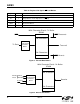
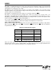
2.2.3.3. Flow Control
The ISOmodem supports flow control through RTS
/CTS and XON/XOFF. RTS (request-to-send) is a control signal
from the terminal (DTE) to the modem (DCE) indicating data may be sent from the modem to the terminal. CTS
(clear-to-send) is a control signal from the modem (DCE) to the terminal (DTE) indicating data may be sent from
the terminal to the modem for transmission to the remote modem. This arrangement is typically referred to as
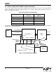
hardware flow control. There is a 14-character FIFO and a 1024 character elastic transmit buffer (see Figure 3).
CTS
goes inactive (high) when the 1024 character buffer reaches 796 characters, then reasserts (low) when the
buffer falls below 128 characters. There is no provision to compensate for FIFO overflow. Data received on TXD
when the FIFO is full are lost.
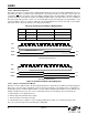
XON/XOFF is a software flow control method in which the modem and terminal control the data flow by sending
XON characters (^Q/0x11) and XOFF characters (^S/0x13). XON/XOFF flow control is enabled on the ISOmodem
with AT\Q4.
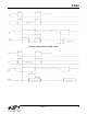
DCD
does not de-assert during a retrain (see Table 45: S9, Carrier presence timer and S10, Carrier loss timer).
CTS
always deasserts during initial training, retrain, and at disconnect regardless of the \Qn setting. For \Q0 CTS,
flow control is disabled; CTS
is inactive during data transfer. The modem remains in the data mode during normal
automatic retrains. The host can force a retrain by escaping to the command mode and sending ATO1 or ATO2.
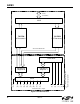
The DCD
and RI pins can be used as hardware monitors of the carrier detect and ring signals. Additionally, the INT
pin can be programmed to monitor the bits in register U70 listed in Table 20. The RI, PPD, OCD, CID, and RST bits
are sticky, and the AT:I command reads and clears these signals and deactivates the INT
pin if INT is enabled.
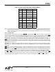
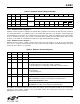
Table 19. Serial Formats Detected in Autobaud Mode
Symbol Data bits Parity Stop bits
7N1 7 None (mark) 1
7N2 7 None (mark) 2
7S1 7 None (space) 1
7O1 7 Odd 1
7E1 7 Even 1
8N1 8 None (mark) 1
8E1 8 Even 1
8O1 8 Odd 1
9N1 9 None (mark) 1