
- Silicon Laboratories, Inc. Home Security System User Manual

Si4421
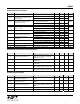
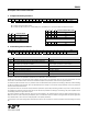
Bits 9-8 (d1 to d0): VDI (valid data indicator) signal response time setting:
d1 d0 Response
0 0 Fast
0 1 Medium
1 0 Slow
1 1 Always on
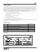
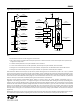
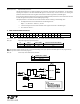
VDI Logic Diagram:
d0
R/S FF
LOGIC HIGH
d1CR_LOCK
DRSSI
DQD
IN0
IN1
IN2
IN3
SEL1
SEL0
Y
Q
DQD
CR_LOCK
DQD
DRSSI
SET
CLR
VDI
MUX
FAST
MEDIUM
SLOW
er *
CLR
Note:
* For details see the Power Management Command
Slow mode: The VDI signal will go high only if the DRSSI, DQD and the CR_LOCK (Clock Recovery Locked) signals present at the same
time. It stays high until any of the abovementioned signals present; it will go low when all the three input signals are low.
Medium mode: The VDI signal will be active when the CR_LOCK signal and either the DRSSI or the DQD signal is high. The valid data
indicator will go low when either the CR_LOCK gets inactive or both of the DRSSI or DQD signals go low.
Fast mode: The VDI signal follows the level of the DQD signal.
Always mode: VDI is connected to logic high permanently. It stays always high independently of the receiving parameters.
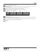
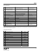
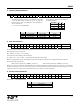
Bits 7-5 (i2 to i0): Receiver baseband bandwidth (BW) select:
i2 i1 i0 BW [kHz]
0 0 0 Reserved
0 0 1 400
0 1 0 340
0 1 1 270
1 0 0 200
1 0 1 134
1 1 0 67
1 1 1 Reserved
Note: For the optimal bandwidth settings at different data rates see the table on page 37.
18