
Specifications


Si4730/31/34/35-D60
16 Rev. 1.1
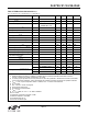
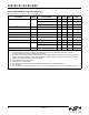
Table 9. AM/SW/LW Receiver Characteristics
1,2
(V
A
= 2.7 to 5.5 V, V
A
= 1.62 to 3.6 V, T
A
= –20 to 85 °C)
Parameter Symbol Test Condition Min Typ Max Unit
Input Frequency f
RF
Long Wave (LW) 153 — 279 kHz
Medium Wave (AM) 520 — 1710 kHz
Short Wave (SW) 2.3 — 26.1 MHz
Sensitivity
3,4,5
(S+N)/N = 26 dB — 25 35 µV EMF
Large Signal Voltage Handling
5,6
THD < 8% — 300 — mV
RMS
Power Supply Rejection Ratio
5
∆V
DD
=100 mV
RMS
, 100 Hz — 40 — dB
Audio Output Voltage
3,7
54 60 67 mV
RMS
Audio S/N
3,4,7
—60— dB
Audio THD
3,7
— 0.1 0.5 %
Antenna Inductance
5,8
Long Wave (LW) — 2800 — µH
Medium Wave (AM) 180 — 450 µH
Powerup Time
5
From powerdown — — 110 ms
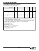
Notes:
1. Additional testing information is available in “AN388: Si470x/1x/2x/3x/4x Evaluation Board Test Procedure.”
Volume = maximum for all tests. Tested at RF = 520 kHz.
2. To ensure proper operation and receiver performance, follow the guidelines in “AN383: Si47xx Antenna, Schematic,
Layout, and Design Guidelines.” Silicon Laboratories will evaluate schematics and layouts for qualified customers.
3. FMOD = 1 kHz, 30% modulation, 2 kHz channel filter.
4. B
AF
= 300 Hz to 15 kHz, A-weighted.
5. Guaranteed by characterization.
6. See “AN388: Si470x/1x/2x/3x/4x Evaluation Board Test Procedure” for evaluation method.
7. V
IN
= 5 mVrms.
8. Stray capacitance on antenna and board must be < 10 pF to achieve full tuning range at higher inductance levels.