
User`s guide


Si47xx-EVB
28 Rev. 0.8
3. Recommended Hardware Setup
The Si47xx-EVB can be configured for FM transmit, FM receive, WB receive, or AM/SW/LW receive. The following
is a description of how to correctly configure the device for either mode of operation.
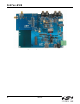
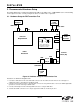
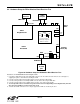
3.1. Hardware Setup for FM Transmitter Test
Figure 19. Hardware Setup for FM Transmitter Test
Instructions for Si471x/2x daughtercards:
1. Connect the USB cable from PC to the EVB USB connector J79. The USB connection will serve as a dual purpose:
supplying the power to the EVB and controlling the EVB.
2. Connect an analog audio generator to the RCA input connector J7 using an RCA cable or connect an SPDIF digital audio
generator to connector J19 using an SPDIF cable.
3. Connect an RF analyzer from the FM output SMA connector J1 using an SMA cable.
4. J19 and J30 S/PDIF connections are no longer supported on EVBs as of February 14, 2011.
Si471x/2x
Daughterboard
RF
Analyzer
Analog
Audio
Generator
PC
w/ USB
port
J28
RCA OUT
USB
FM IN
J6
J79
USB Cable
SMA Cable
RCA Cable
EXT pwr
USB pwr
EXT Jack
SW1
Terminal
Block (TB)
J76
J78
Si47xx
Baseboard
J1
FM OUT RCA IN
J7
J19
J30
S/PDIF
Audio
Generator
J44 J45
Jumpers
Setting
J41
TX
RX
TX
RX
DCLK
GPIO3
Note: J44 and J45 are
automatically configured in
EVB Rev1.3 and later