
User`s guide

Si47xx-EVB
Rev. 0.8 9
Baseboard audio I/O connectors:
J6 RCA output
J30 Line output
Note: Line output will not be supported on new EVBs as of February 14, 2011.
Baseboard clock connectors/devices:
X1 32.768 kHz crystal oscillator
J52 Solder bump: select internal RCLK from oscillator
J54 Ext RCLK SMA connector input
J57 Jumper: Enable or Disable Int RCLK
Baseboard MCU connectors/devices:
U22 C8051F342 MCU
J79 USB connector to communicate with the MCU
J74 JTAG connector for the MCU
PB1 Push button to reset the MCU
D1 LED to confirm power supply to the MCU
Baseboard to Daughtercard connectors:
J27 Si47xx daughtercard connector
J75 Expansion card connector (reserved)
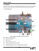
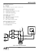
2.1.1. Power Supply Network
Figure 2. Power Supply Block Diagram
SW1
J78
EXT
LDO
1.25–3.9 V
(R73)
LDO
1.25–7 V
(R74)
Jumper
J68
Jumper
J69
Daughterboard
Si47xx
VIO
10
11
VDD
ADJ
TB
+3.3 V
LDO
+3.3 V
(U17)
J79
USB
J76
Terminal
Block (TB)
Gnd
Vdd
Vio
Vm
ADJ
+3.3 V
TB
+3.3 V
TB
Vmcu
Jumper
J61
VIO
VDD
J77
BATT