
User guide


34 www.xilinx.com AC701 Evaluation Board
UG952 (v1.1) January 30, 2013
Chapter 1: AC701 Evaluation Board Features
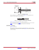
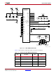
PCIe lane width/size is selected via jumper J12 (Figure 1-19). The default lane size
selection is 4-lane (J12 pins 3 and 4) jumpered).
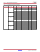
Table 1-12, page 32 lists the PCIe edge connector connections.
For more information refer to UG476, 7 Series FPGAs GTP Transceivers User Guide and
UG477 7 Series FPGAs Integrated Block for PCI Express User Guide (AXI).
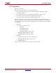
SFP/SFP+ Connector
[Figure 1-2, callout 13]
The AC701 board contains a small form-factor pluggable (SFP+) connector and cage
assembly (P3) that accepts SFP or SFP+ modules.
Figure 1-20 shows the SFP+ module
connector circuitry.
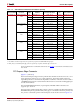
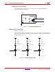
X-Ref Target - Figure 1-18
Figure 1-18: PCI Express Clock
X-Ref Target - Figure 1-19
Figure 1-19: PCI Express Lane Size Select Jumper J12
UG952_c1_18_100312
PCI Express
Four-Lane
Edge connector
GND
GND
A15
A13
A14
P1
REFCLK+
A12
GND
C188
0.01μF 25V
X7R
C189
0.01μF 25V
X7R
PCIE_CLK_Q0_P
PCIE_CLK_Q0_N
PCIE_CLK_Q0_C_P
PCIE_CLK_Q0_C_N
OE
REFCLK-
UG952_c1_19_100312
PCIE_PRSNT_B
PCIE_PRSNT_X1
PCIE_PRSNT_X4
J12
1
3
2
4