
User guide


38 www.xilinx.com AC701 Evaluation Board
UG952 (v1.1) January 30, 2013
Chapter 1: AC701 Evaluation Board Features
Ethernet PHY Clock Source
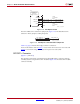
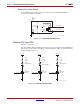
A 25.00 MHz, 50 ppm crystal at X1 is the clock source for the 88E1116R PHY at U12.
Figure 1-21 shows the clock source.
Ethernet PHY User LEDs
[Figure 1-2, callout 20]
The three Ethernet PHY user LEDs shown in Figure 1-22 are located near the RJ45 Ethernet
jack P4. The on/off state for each LED is software dependent and has no specific meaning
at Ethernet PHY power-on.
X-Ref Target - Figure 1-21
Figure 1-21: Ethernet PHY Clock Source
UG952_c1_21_100312
GND
R275
1.0M 5%
C406
18pF 50V
NPO
NC
NC
C405
18pF 50V
NPO
PHY_XTAL_OUT
GND2
GND1
X2
X1
X1
25.00 MHz
50 ppm
PHY_XTAL_IN
3
4
1
2
X-Ref Target - Figure 1-22
Figure 1-22: Ethernet PHY User LEDs
Q3
NDS331N
460 mW
DS12
LED-GRN-SMT
PHY_LED1
R280
261Ω
1/10W
VCC3V3
GND
Q3
NDS331N
460 mW
DS11
LED-GRN-SMT
PHY_LED2
R279
261Ω
1/10W
VCC3V3
GND
Q3
NDS331N
460 mW
DS13
LED-GRN-SMT
PHY_LED0
R281
261Ω
1/10W
VCC3V3
GND
UG952_c1_22_100312