
User guide


AC701 Evaluation Board www.xilinx.com 39
UG952 (v1.1) January 30, 2013
Feature Descriptions
Refer to the Marvell 88E1116R Alaska Gigabit Ethernet transceiver datasheet for details
concerning the use of the Ethernet PHY user LEDs. They are referred to in the datasheet as
LED0, LED1, and LED2. The product brief and other product information for the Marvell
88E1116R Alaska Gigabit ethernet transceiver is available at:
http://www.marvell.com/transceivers/alaska-gbe/
The Marvell 88E1116R PHY datasheet may be obtained under NDA with Marvell, whose
contact information may be found at:
http://www.marvell.com.
USB-to-UART Bridge
[Figure 1-2, callout 16]
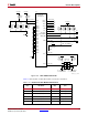
The AC701 board contains a Silicon Labs CP2103GM USB-to-UART bridge device (U44)
which allows a connection to a host computer with a USB port. The USB cable is supplied
in the Evaluation Kit (standard-A plug to host computer, mini-B plug to AC701 board
connector J17). The CP2103GM is powered by the USB 5V provided by the host PC when
the USB cable is plugged into the USB port on the AC701 board.
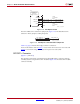
Xilinx UART IP is expected to be implemented in the FPGA fabric. The FPGA supports the
USB-to-UART bridge using four signal pins: Transmit (TX), Receive (RX), Request to Send
(RTS), and Clear to Send (CTS).
Silicon Labs provides royalty-free Virtual COM Port (VCP) drivers for the host computer.
These drivers permit the CP2103GM USB-to-UART bridge to appear as a COM port to
communications application software (for example, TeraTerm or HyperTerm) that runs on
the host computer. The VCP device drivers must be installed on the host PC prior to
establishing communications with the AC701 board.
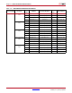
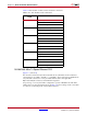
Table 1-17 shows the USB signal definitions at J17.
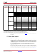
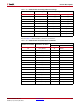
Table 1-18 shows the USB connections between the FPGA and the UART.
Table 1-17: USB J17 Mini-B Receptacle Pin Assignments and Signal Definitions
USB Receptacle
Pins (J17)
Receptacle Pin
Name
Schematic
Net Name
Description
U44 Pin
(CP2103GM)
U44 Pin Name
(CP2103GM)
1VBUS
USB_UART_
VBUS
+5V from host system -
U12 CP2103 power
7, 8 REGIN, VBUS
2 D_N USB_D_N
Bidirectional
differential serial data
(N-side)
4D-
3 D_P USB_D_P
Bidirectional
differential serial data
(P-side)
3D+
4GND
USB_UART_
GND
Signal ground 2, 29 GND, GND