
User guide


AC701 Evaluation Board www.xilinx.com 43
UG952 (v1.1) January 30, 2013
Feature Descriptions
Table 1-20 lists the connections between the codec and the HDMI connector P2.
Information about the ADV7511 is available on the Analog Devices website at
http://www.analog.com/en/index.html.
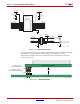
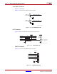
LCD Character Display
[Figure 1-2, callout 18]
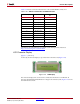
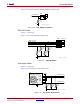
A 2-line by 16-character display is provided on the AC701 board (Figure 1-24).
The character display runs at 5.0V and is connected to the FPGA's 3.3V HP bank 14
through a TI TXS0108E 8-bit bidirectional voltage level translator (U45).
Figure 1-25 shows
the LCD interface circuit.
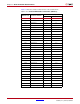
Table 1-20: ADV7511 Connections to HDMI Connector
ADV7511 (U48) Schematic Net Name
HDMI Connector P2
Pin
36 HDMI_D0_P 7
35 HDMI_D0_N 9
40 HDMI_D1_P 4
39 HDMI_D1_N 6
43 HDMI_D2_P 1
42 HDMI_D2_N 3
33 HDMI_CLK_P 10
32 HDMI_CLK_N 12
54 HDMI_DDCSDA 16
53 HDMI_DDCSCL 15
52 HDMI_HEAC_P 14
51 HDMI_HEAC_N 19
48 HDMI_CRC 13
X-Ref Target - Figure 1-24
Figure 1-24: LCD Display
UG952_c1_24_101612
LCD Display (16 x 2)