
User guide


48 www.xilinx.com AC701 Evaluation Board
UG952 (v1.1) January 30, 2013
Chapter 1: AC701 Evaluation Board Features
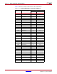
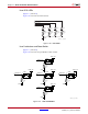
User GPIO LEDs
[Figure 1-2, callout 21]
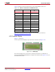
Figure 1-28 shows the user LED circuits.
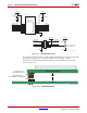
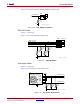
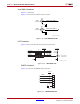
User Pushbuttons and Reset Switch
[Figure 1-2, callout 22]
Figure 1-29 shows the user pushbutton switch circuits.
X-Ref Target - Figure 1-28
Figure 1-28: User LEDs
UG952_c1_28_100312
R147
49.9Ω
1%
DS2
R148
49.9Ω
1%
DS3
R149
49.9Ω
1%
DS4
R150
49.9Ω
1%
GND
DS5
GPIO_LED_2
GPIO_LED_0
GPIO_LED_1
GPIO_LED_3
X-Ref Target - Figure 1-29
Figure 1-29: User Pushbuttons
UG952_c1_29_011813
FPGA_1V5
GPIO SW C
R39
4.7kΩ
0.1 W
5%
GND
4
3 2
1
SW6
FPGA_1V5
GPIO SW N
R36
4.7kΩ
0.1 W
5%
GND
4
3 2
1
SW3
FPGA_1V5
GPIO SW S
R38
4.7kΩ
0.1 W
5%
GND
4
3 2
1
SW5
FPGA_1V5
GPIO SW W
R40
4.7kΩ
0.1 W
5%
GND
4
3 2
1
SW7
FPGA_1V5
GPIO SW E
R37
4.7kΩ
0.1 W
5%
GND
4
3 2
1
SW4