
User guide

AC701 Evaluation Board www.xilinx.com 67
UG952 (v1.1) January 30, 2013
Feature Descriptions
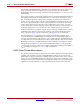
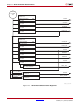
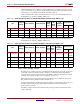
Power Management
[Figure 1-2, callout 30]
The AC701 board uses power regulators and PMBus compliant system controllers from
Texas Instruments to supply core and auxiliary voltages. The Texas Instruments Fusion
Digital Power graphical user interface is used to monitor the voltage and current levels of
the board power modules.
The AC701 board power distribution diagram is shown in Figure 1-43.
The pcb layout and power system design meets the recommended criteria described in the
UG483, 7 Series FPGAs PCB Design and Pin Planning Guide.
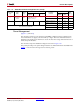
V
MGTAVTT
SENSE
NA
MGTAVTT REMOTE SENSE DIVIDED
TO DELIVER 0.6V ON
MGTAVTT_XADC_P
MGTAVTT_XADC_P 24 S6A 101
MGTAVTT_SENSE_N 6 S6B
I MGTAVTT CS 0A-1.5A U23 100 0V-0.756V
MGTAVTT_XADC_CS_P 25 S7A 110
MGTAVTT_XADC_CS_N 5 S7B
NOT USED NOT CONNECTED)
NC 26 S8A 111
NC 4 S8B
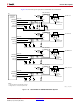
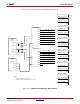
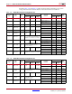
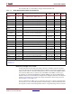
Table 1-30: XADC Measurements through Mux U13 (Cont’d)
Measurement
Type
Rail
Name
Current
Range
I
sense
Op Amp
Schematic
Net Name
8-to-1 Multiplexer U14
Mux
A[2:0]Reference
Designator
Gain V
o
Range
Pin
Number
Pin
Name