
- Silicon Laboratories, Inc. Clock User Manual

Si53xx-RM
Rev. 0.5 101
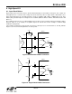
7.11.9. Device Interrupts
Alarms on internal real-time status bits such as LOS1_INT, FOS1_INT, etc. cause their associated interrupt flags
(LOS1_FLG, FOS1_FLG, etc.) to be set and held. The interrupt flag bits can be individually masked or unmasked
with respect to the output interrupt pin. Once an interrupt flag bit is set, it will remain high until the register location
is written with a “0” to clear the flag.
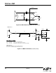
7.12. Device Reset
Upon powerup or asserting Reset via the RST pin or software, the device internally executes a power-on-reset
(POR) which resets the internal device logic and tristates the device outputs. The device waits for configuration
commands and the receipt of the ICAL = 1 command to start its calibration. Any changes to the CMODE pin
require that RST
be toggled to reset the part. The power-up default register values are given in the data sheets for
these parts.
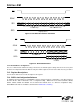
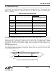
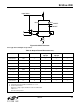
Table 54. Lock Detect Retrigger Time (LOCKT)
LOCKT[2:0] Retrigger Time (ms)
000 106
001 53
010 26.5
011 13.3
100 6.6 (value after reset)
101 3.3
110 1.66
111 .833