C8051F330/1 8k ISP FLASH MCU Family ANALOG PERIPHERALS - 10-Bit ADC (‘F330 only) • Up to 200 ksps • Up to 16 External Single-Ended or Differential Inputs • VREF from Internal VREF, External Pin or VDD • Internal or External Start of Conversion Source • Built-in Temperature Sensor - 10-Bit Current Output DAC (‘F330 only) - Comparator • Programmable Hysteresis and Response Time • Configurable as Interrupt or Reset Source • Low Current (0.
C8051F330/1 Notes 2 Rev. 1.
C8051F330/1 TABLE OF CONTENTS 1. SYSTEM OVERVIEW .........................................................................................................13 1.1. CIP-51™ Microcontroller Core ......................................................................................17 1.1.1. Fully 8051 Compatible ..........................................................................................17 1.1.2. Improved Throughput ...................................................................................
C8051F330/1 9.2.5. Stack ...................................................................................................................74 9.2.6. Special Function Registers.....................................................................................75 9.2.7. Register Descriptions .............................................................................................78 9.3. Interrupt Handler ....................................................................................................
C8051F330/1 15.2. SMBus Configuration....................................................................................................128 15.3. SMBus Operation ..........................................................................................................129 15.3.1. Arbitration............................................................................................................129 15.3.2. Clock Low Extension.................................................................................
C8051F330/1 19. PROGRAMMABLE COUNTER ARRAY .......................................................................185 19.1.PCA Counter/Timer.......................................................................................................186 19.2. Capture/Compare Modules............................................................................................187 19.2.1. Edge-triggered Capture Mode .............................................................................188 19.2.2.
C8051F330/1 LIST OF FIGURES AND TABLES 1. SYSTEM OVERVIEW Table 1.1. Product Selection Guide ......................................................................................14 Figure 1.1. C8051F330 Block Diagram.................................................................................15 Figure 1.2. C8051F331 Block Diagram.................................................................................16 Figure 1.3. Comparison of Peak MCU Execution Speeds.........................................
C8051F330/1 Figure 5.18. ADC Window Compare Example: Left-Justified Differential Data ...................49 Table 5.1. ADC0 Electrical Characteristics..........................................................................50 6. 10-BIT CURRENT MODE DAC (IDA0, C8051F330 ONLY) Figure 6.1. IDA0 Functional Block Diagram ........................................................................51 Figure 6.2. IDA0 Data Word Mapping..................................................................................
C8051F330/1 11. FLASH MEMORY Table 11.1. FLASH Electrical Characteristics .......................................................................98 Figure 11.1. FLASH Program Memory Map ........................................................................100 Figure 11.2. PSCTL: Program Store R/W Control ................................................................100 Figure 11.3. FLKEY: FLASH Lock and Key Register .........................................................101 Figure 11.4.
C8051F330/1 Figure 15.8. Typical Master Transmitter Sequence...............................................................139 Figure 15.9. Typical Master Receiver Sequence ...................................................................140 Figure 15.10. Typical Slave Receiver Sequence ...................................................................141 Figure 15.11. Typical Slave Transmitter Sequence ...............................................................142 Table 15.4. SMBus Status Decoding..
C8051F330/1 Figure 18.8. TL1: Timer 1 Low Byte ....................................................................................176 Figure 18.9. TH0: Timer 0 High Byte ...................................................................................176 Figure 18.10. TH1: Timer 1 High Byte .................................................................................176 Figure 18.11. Timer 2 16-Bit Mode Block Diagram .............................................................177 Figure 18.12.
C8051F330/1 Notes 12 Rev. 1.
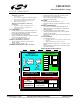
C8051F330/1 1. SYSTEM OVERVIEW C8051F330/1 devices are fully integrated mixed-signal System-on-a-Chip MCUs. Highlighted features are listed below. Refer to Table 1.1 for specific product feature selection.
MIPS (Peak) FLASH Memory RAM Calibrated Internal 24.5 MHz Oscillator Internal 80 kHz Oscillator SMBus/I2C Enhanced SPI UART Timers (16-bit) Programmable Counter Array Digital Port I/Os 10-bit 200ksps ADC 10-bit Current Output DAC Internal Voltage Reference Temperature Sensor Analog Comparator Package C8051F330/1 Table 1.1. Product Selection Guide C8051F330 25 8k 768 3 3 3 3 3 4 3 17 3 3 3 3 3 MLP-20 C8051F331 25 8k 768 3 3 3 3 3 4 3 17 - 3 MLP-20 14 Rev. 1.
C8051F330/1 Figure 1.1. C8051F330 Block Diagram Port 0 Latch UART VDD Analog/Digital Power GND C2D Debug HW Reset /RST/C2CK POR XTAL1 XTAL2 BrownOut External Oscillator Circuit 24.5MHz (2%) Internal Oscillator P 0 Timer 0, 1, 2, 3 System Clock 8 0 5 1 3-Chnl PCA/ WDT 8kbyte FLASH SMBus SPI 256 byte SRAM D r v X B A R Port 1 Latch 512 byte XRAM P 1 C o SFR Bus r e D r v CP0 80 kHz Internal Oscillator P0.0/VREF P0.1/IDA0 P0.2/XTAL1 P0.3/XTAL2 P0.4/TX P0.5/RX P0.6/CNVST P0.7 P1.0 P1.
C8051F330/1 Figure 1.2. C8051F331 Block Diagram Port 0 Latch P0.0 UART VDD Analog/Digital Power GND C2D Debug HW Reset /RST/C2CK POR XTAL1 XTAL2 BrownOut External Oscillator Circuit 24.5MHz (2%) Internal Oscillator System Clock 8 0 5 1 3-Chnl PCA/ WDT 8kbyte FLASH SMBus SPI 256 byte SRAM D r v 512 byte XRAM P0.1 P0.2/XTAL1 P0.3/XTAL2 P0.4/TX P0.5/RX P0.6 P0.7 X B A R P1.0 Port 1 Latch P 1 C o SFR Bus r e D r v P1.1 P1.2 P1.3 P1.4 P1.5 P1.6 P1.
C8051F330/1 1.1. CIP-51™ Microcontroller Core 1.1.1. Fully 8051 Compatible The C8051F330/1 family utilizes Silicon Labs' proprietary CIP-51 microcontroller core. The CIP-51 is fully compatible with the MCS-51™ instruction set; standard 803x/805x assemblers and compilers can be used to develop software.
C8051F330/1 1.1.3. Additional Features The C8051F330/1 SoC family includes several key enhancements to the CIP-51 core and peripherals to improve performance and ease of use in end applications. The extended interrupt handler provides 14 interrupt sources into the CIP-51 (as opposed to 7 for the standard 8051), allowing numerous analog and digital peripherals to interrupt the controller. An interrupt driven system requires less intervention by the MCU, giving it more effective throughput.
C8051F330/1 1.2. On-Chip Memory The CIP-51 has a standard 8051 program and data address configuration. It includes 256 bytes of data RAM, with the upper 128 bytes dual-mapped. Indirect addressing accesses the upper 128 bytes of general purpose RAM, and direct addressing accesses the 128 byte SFR address space. The lower 128 bytes of RAM are accessible via direct and indirect addressing.
C8051F330/1 1.3. On-Chip Debug Circuitry The C8051F330/1 devices include on-chip Silicon Labs 2-Wire (C2) debug circuitry that provides non-intrusive, full speed, in-circuit debugging of the production part installed in the end application. Silicon Labs' debugging system supports inspection and modification of memory and registers, breakpoints, and single stepping. No additional target RAM, program memory, timers, or communications channels are required.
C8051F330/1 1.4. Programmable Digital I/O and Crossbar C8051F330/1 devices include 17 I/O pins (two byte-wide Ports and one 1-bit-wide Port). The C8051F330/1 Ports behave like typical 8051 Ports with a few enhancements. Each Port pin may be configured as an analog input or a digital I/O pin. Pins selected as digital I/Os may additionally be configured for push-pull or open-drain output.
C8051F330/1 1.6. Programmable Counter Array An on-chip Programmable Counter/Timer Array (PCA) is included in addition to the four 16-bit general purpose counter/timers. The PCA consists of a dedicated 16-bit counter/timer time base with three programmable capture/compare modules.
C8051F330/1 1.7. 10-Bit Analog to Digital Converter The C8051F330/1 devices include an on-chip 10-bit SAR ADC with a 16-channel differential input multiplexer. With a maximum throughput of 200 ksps, the ADC offers true 10-bit linearity with an INL and DNL of ±1LSB. The ADC system includes a configurable analog multiplexer that selects both positive and negative ADC inputs.
C8051F330/1 1.8. Comparators C8051F330/1 devices include an on-chip voltage comparator that is enabled/disabled and configured via user software. Port I/O pins may be configured as comparator inputs via a selection mux. Two comparator outputs may be routed to a Port pin if desired: a latched output and/or an unlatched (asynchronous) output. Comparator response time is programmable, allowing the user to select between high-speed and low-power modes. Positive and negative hysteresis are also configurable.
C8051F330/1 1.9. 10-bit Current Output DAC The C8051F330 device includes a 10-bit current-mode Digital-to-Analog Converter (IDA0). The maximum current output of the IDA0 can be adjusted for three different current settings; 0.5 mA, 1 mA, and 2 mA. IDA0 features a flexible output update mechanism which allows for seamless full-scale changes and supports jitter-free updates for waveform generation.
C8051F330/1 2. ABSOLUTE MAXIMUM RATINGS Table 2.1. Absolute Maximum Ratings* PARAMETER CONDITIONS MIN TYP MAX UNITS Ambient temperature under bias -55 125 °C Storage Temperature -65 150 °C Voltage on any Port I/O Pin or /RST with respect to GND -0.3 5.8 V Voltage on VDD with respect to GND -0.3 4.
C8051F330/1 3. GLOBAL DC ELECTRICAL CHARACTERISTICS Table 3.1. Global DC Electrical Characteristics -40°C TO +85°C, 25 MHZ SYSTEM CLOCK UNLESS OTHERWISE SPECIFIED. PARAMETER CONDITIONS Digital Supply Voltage MIN TYP MAX UNITS VRST† 3.0 3.6 V Digital Supply Current with CPU active VDD=2.7V, Clock=25MHz VDD=2.7V, Clock=1MHz VDD=2.7V, Clock = 80kHz VDD=2.7V, Clock=32kHz 6.4 0.36 20 9 mA mA µA µA Digital Supply Current with CPU inactive (not accessing FLASH) VDD=2.7V, Clock=25MHz VDD=2.
C8051F330/1 4. PINOUT AND PACKAGE DEFINITIONS Table 4.1. Pin Definitions for the C8051F330/1 Name Pin Numbers VDD 3 Power Supply Voltage. GND 2 Ground. /RST/ 4 C2CK P2.0/ 5 C2D P0.0/ 1 VREF P0.1 20 XTAL1 P0.3/ D I/O Clock signal for the C2 Debug Interface. D I/O Port 3.0. See Section 14 for a complete description. D I/O Bi-directional data signal for the C2 Debug Interface. D I/O or Port 0.0. See Section 14 for a complete description. A In 18 External VREF input.
C8051F330/1 Table 4.1. Pin Definitions for the C8051F330/1 Name Pin Numbers P0.6/ 15 CNVSTR Type Description D I/O or Port 0.6. See Section 14 for a complete description. A In D In ADC0 External Convert Start or IDA0 Update Source Input. See Section 5 and Section 6 for a complete description. P0.7 14 D I/O or Port 0.7. See Section 14 for a complete description. A In P1.0 13 D I/O or Port 1.0. See Section 14 for a complete description. A In P1.1 12 D I/O or Port 1.1.
C8051F330/1 30 P0.1 P0.2 P0.3 P0.4 P0.5 19 18 17 16 GND 20 Figure 4.1. MLP-20 Pinout Diagram (Top View) P1.1 5 11 P1.2 P2.0/C2D 10 12 P1.3 4 /RST/C2CK 9 P1.0 P1.4 13 3 8 GND VDD P1.5 P0.7 7 14 2 P1.6 TOP VIEW GND 6 P0.6 1 P1.7 15 P0.0 Rev. 1.
C8051F330/1 Figure 4.2. MLP-20 Package Drawing L 5 11 D2 12 D2 2 R E2 2 e 3 2 1 14 15 16 17 18 19 DETAIL 1 20 13 4xe E 4 E2 b Table 4.2. MLP-20 Package Dimensions 10 9 8 7 6 Bottom View 4xe D MAX 1.00 0.05 1.00 0.30 2.25 2.25 0.65 - A1 A3 e MM TYP 0.90 0.02 0.65 0.25 0.23 4.00 2.15 4.00 2.15 0.5 0.55 20 5 5 0.435 0.435 0.18 0.18 A A2 Side View A A1 A2 A3 b D D2 E E2 e L N ND NE R AA BB CC DD MIN 0.80 0 0 0.18 2.00 2.00 0.45 0.09 - DETAIL 1 CC DD BB AA Rev. 1.
C8051F330/1 Figure 4.3. Typical MLP-20 Solder Mask 0.50 mm 0.35 mm 0.50 mm 0.10 mm 0.20 mm 0.30 mm 0.85 mm 0.20 mm 0.50 mm Top View 0.20 mm 0.60 mm 0.30 mm e 0.70 mm 0.60 mm 0.20 mm L E2 0.20 mm 0.30 mm 0.50 mm 0.35 mm 0.10 mm 0.85 mm E 32 Rev. 1.1 D b D2 0.
C8051F330/1 Figure 4.4. Typical MLP-20 Landing Diagram 0.50 mm 0.35 mm 0.50 mm 0.10 mm 0.20 mm 0.30 mm 0.85 mm 0.20 mm 0.50 mm Top View b 0.20 mm D e D2 Optional GND Connection 0.20 mm L E2 0.30 mm 0.50 mm 0.35 mm 0.10 mm 0.85 mm E Rev. 1.
C8051F330/1 Notes 34 Rev. 1.
C8051F330/1 5. 10-BIT ADC (ADC0, C8051F330 ONLY) The ADC0 subsystem for the C8051F330 consists of two analog multiplexers (referred to collectively as AMUX0) with 16 total input selections, and a 200 ksps, 10-bit successive-approximation-register ADC with integrated trackand-hold and programmable window detector. The AMUX0, data conversion modes, and window detector are all configurable under software control via the Special Function Registers shown in Figure 5.1.
C8051F330/1 5.1. Analog Multiplexer AMUX0 selects the positive and negative inputs to the ADC. Any of the following may be selected as the positive input: Ports0-1, the on-chip temperature sensor, or the positive power supply (VDD). Any of the following may be selected as the negative input: Ports0-1, VREF, or GND. When GND is selected as the negative input, ADC0 operates in Single-ended Mode; all other times, ADC0 operates in Differential Mode.
C8051F330/1 5.2. Temperature Sensor The typical temperature sensor transfer function is shown in Figure 5.2. The output voltage (VTEMP) is the positive ADC input when the temperature sensor is selected by bits AMX0P4-0 in register AMX0P. Figure 5.2. Typical Temperature Sensor Transfer Function (Volts) 1.000 0.900 0.800 VTEMP = 2.86(TEMPC) + 776 mV 0.700 0.600 0.500 -50 0 50 Rev. 1.
C8051F330/1 5.3. Modes of Operation ADC0 has a maximum conversion speed of 200 ksps. The ADC0 conversion clock is a divided version of the system clock, determined by the AD0SC bits in the ADC0CF register (system clock divided by (AD0SC + 1) for 0 ≤ AD0SC ≤ 31). 5.3.1. Starting a Conversion A conversion can be initiated in one of six ways, depending on the programmed states of the ADC0 Start of Conversion Mode bits (AD0CM2-0) in register ADC0CN. Conversions may be initiated by one of the following: 1.
C8051F330/1 5.3.2. Tracking Modes The AD0TM bit in register ADC0CN controls the ADC0 track-and-hold mode. In its default state, the ADC0 input is continuously tracked, except when a conversion is in progress. When the AD0TM bit is logic 1, ADC0 operates in low-power track-and-hold mode. In this mode, each conversion is preceded by a tracking period of 3 SAR clocks (after the start-of-conversion signal).
C8051F330/1 5.3.3. Settling Time Requirements When the ADC0 input configuration is changed (i.e., a different AMUX0 selection is made), a minimum tracking time is required before an accurate conversion can be performed. This tracking time is determined by the AMUX0 resistance, the ADC0 sampling capacitance, any external source resistance, and the accuracy required for the conversion. Note that in low-power tracking mode, three SAR clocks are used for tracking at the start of every conversion.
C8051F330/1 Figure 5.5. AMX0P: AMUX0 Positive Channel Select Register R R R R/W R/W R/W R/W R/W Reset Value - - - AMX0P4 AMX0P3 AMX0P2 AMX0P1 AMX0P0 00011111 Bit7 Bit6 Bit5 Bit4 Bit3 Bit2 Bit1 Bit0 SFR Address: 0xBB Bits7-5: Bits4-0: UNUSED. Read = 000b; Write = don’t care. AMX0P4-0: AMUX0 Positive Input Selection AMX0P4-0 00000 00001 00010 00011 00100 00101 00110 00111 01000 01001 01010 01011 01100 01101 01110 01111 10000 10001 10010 - 11111 ADC0 Positive Input P0.0 P0.1 P0.
C8051F330/1 Figure 5.6. AMX0N: AMUX0 Negative Channel Select Register R R R - - - Bit7 Bit6 Bit5 R/W R/W R/W R/W R/W AMX0N4 AMX0N3 AMX0N2 AMX0N1 AMX0N0 Bit4 Bit3 Bit2 Bit1 Bit0 Reset Value 00011111 SFR Address: 0xBA Bits7-5: Bits4-0: UNUSED. Read = 000b; Write = don’t care. AMX0N4-0: AMUX0 Negative Input Selection. Note that when GND is selected as the Negative Input, ADC0 operates in Single-ended mode. For all other Negative Input selections, ADC0 operates in Differential mode.
C8051F330/1 Figure 5.7. ADC0CF: ADC0 Configuration Register R/W R/W R/W R/W R/W R/W R R Reset Value AD0SC4 AD0SC3 AD0SC2 AD0SC1 AD0SC0 AD0LJST - - 11111000 Bit7 Bit6 Bit5 Bit4 Bit3 Bit2 Bit1 Bit0 SFR Address: 0xBC Bits7-3: AD0SC4-0: ADC0 SAR Conversion Clock Period Bits. SAR Conversion clock is derived from system clock by the following equation, where AD0SC refers to the 5-bit value held in bits AD0SC4-0. SAR Conversion clock requirements are given in Table 5.1.
C8051F330/1 Figure 5.9. ADC0L: ADC0 Data Word LSB Register R/W R/W R/W R/W R/W R/W R/W R/W Reset Value 00000000 Bit7 Bit6 Bit5 Bit4 Bit3 Bit2 Bit1 Bit0 SFR Address: 0xBD Bits7-0: 44 ADC0 Data Word Low-Order Bits. For AD0LJST = 0: Bits 7-0 are the lower 8 bits of the 10-bit Data Word. For AD0LJST = 1: Bits 7-6 are the lower 2 bits of the 10-bit Data Word. Bits 5-0 will always read ‘0’. Rev. 1.
C8051F330/1 Figure 5.10. ADC0CN: ADC0 Control Register R/W R/W AD0EN AD0TM Bit7 Bit6 R/W R/W R/W R/W AD0INT AD0BUSY AD0WINT AD0CM2 Bit5 Bit4 Bit3 Bit2 R/W R/W Reset Value AD0CM1 AD0CM0 00000000 Bit1 Bit0 SFR Address: (bit addressable) Bit7: Bit6: Bit5: Bit4: Bit3: Bits2-0: 0xE8 AD0EN: ADC0 Enable Bit. 0: ADC0 Disabled. ADC0 is in low-power shutdown. 1: ADC0 Enabled. ADC0 is active and ready for data conversions. AD0TM: ADC0 Track Mode Bit.
C8051F330/1 5.4. Programmable Window Detector The ADC Programmable Window Detector continuously compares the ADC0 output registers to user-programmed limits, and notifies the system when a desired condition is detected. This is especially effective in an interrupt-driven system, saving code space and CPU bandwidth while delivering faster system response times. The window detector interrupt flag (AD0WINT in register ADC0CN) can also be used in polled mode.
C8051F330/1 Figure 5.13. ADC0LTH: ADC0 Less-Than Data High Byte Register R/W R/W R/W R/W R/W R/W R/W R/W Reset Value 00000000 Bit7 Bit6 Bit5 Bit4 Bit3 Bit2 Bit1 Bit0 SFR Address: 0xC6 Bits7-0: High byte of ADC0 Less-Than Data Word Figure 5.14. ADC0LTL: ADC0 Less-Than Data Low Byte Register R/W R/W R/W R/W R/W R/W R/W R/W Reset Value Bit7 Bit6 Bit5 Bit4 Bit3 Bit2 Bit1 Bit0 SFR Address: 00000000 0xC5 Bits7-0: Low byte of ADC0 Less-Than Data Word Rev. 1.
C8051F330/1 5.4.1. Window Detector In Single-Ended Mode Figure 5.15 shows two example window comparisons for right-justified, single-ended data, with ADC0LTH:ADC0LTL = 0x0080 (128d) and ADC0GTH:ADC0GTL = 0x0040 (64d). In single-ended mode, the input voltage can range from ‘0’ to VREF * (1023/1024) with respect to GND, and is represented by a 10-bit unsigned integer value.
C8051F330/1 5.4.2. Window Detector In Differential Mode Figure 5.17 shows two example window comparisons for right-justified, differential data, with ADC0LTH:ADC0LTL = 0x0040 (+64d) and ADC0GTH:ADC0GTH = 0xFFFF (-1d). In differential mode, the measurable voltage between the input pins is between -VREF and VREF*(511/512). Output codes are represented as 10bit 2’s complement signed integers.
C8051F330/1 Table 5.1. ADC0 Electrical Characteristics VDD = 3.0 V, VREF = 2.40 V (REFSL=0), -40°C TO +85°C UNLESS OTHERWISE SPECIFIED PARAMETER CONDITIONS MIN TYP MAX UNITS DC ACCURACY Resolution 10 Integral Nonlinearity Differential Nonlinearity Guaranteed Monotonic bits ±0.5 ±1 LSB ±0.
C8051F330/1 6. 10-BIT CURRENT MODE DAC (IDA0, C8051F330 ONLY) The C8051F330 device includes a 10-bit current-mode Digital-to-Analog Converter (IDAC). The maximum current output of the IDAC can be adjusted for three different current settings; 0.5 mA, 1 mA, and 2 mA. The IDAC is enabled or disabled with the IDA0EN bit in the IDA0 Control Register (see Figure 6.3). When IDA0EN is set to ‘0’, the IDAC port pin (P0.1) behaves as a normal GPIO pin.
C8051F330/1 6.1.2. Update Output Based on Timer Overflow Similar to the ADC operation, in which an ADC conversion can be initiated by a timer overflow independently of the processor, the IDAC outputs can use a Timer overflow to schedule an output update event. This feature is useful in systems where the IDAC is used to generate a waveform of a defined sampling rate by eliminating the effects of variable interrupt latency and instruction execution on the timing of the IDAC output.
C8051F330/1 Figure 6.3. IDA0CN: IDA0 Control Register R/W R/W IDA0EN Bit7 R/W R/W R - - Bit4 Bit3 Bit2 IDA0CM Bit6 Bit5 R R/W R/W IDA0OMD Bit1 Bit0 Reset Value 01110010 SFR Address: 0xB9 Bit 7: Bits 6-4: Bits 3-2: Bits 1:0: IDA0EN: IDA0 Enable. 0: IDA0 Disabled. 1: IDA0 Enabled. IDA0CM[2:0]: IDA0 Update Source Select bits. 000: DAC output updates on Timer 0 overflow. 001: DAC output updates on Timer 1 overflow. 010: DAC output updates on Timer 2 overflow.
C8051F330/1 Figure 6.5. IDA0L: IDA0 Data Word LSB Register R/W Bit7 R/W Bit6 R R R R R R Reset Value - - - - - - 00000000 Bit5 Bit4 Bit3 Bit2 Bit1 Bit0 SFR Address: 0x96 Bits 7-6: Bits 5-0: 54 IDA0 Data Word Low-Order Bits. Lower 2 bits of the 10-bit Data Word. UNUSED. Read = 000000b, Write = don’t care. Rev. 1.
C8051F330/1 . Table 6.1. IDAC Electrical Characteristics -40 to +85°C, VDD = 3.0 V Full-scale output current set to 2 mA unless otherwise specified. PARAMETER CONDITIONS MIN TYP MAX UNITS STATIC PERFORMANCE Resolution Integral Nonlinearity Differential Nonlinearity Guaranteed Monotonic 10 bits ±0.5 LSB ±0.5 Output Compliance Range Output Noise IOUT = TBD; RLOAD = TBD ±1 LSB VDD - 1.
C8051F330/1 Notes 56 Rev. 1.
C8051F330/1 7. VOLTAGE REFERENCE (C8051F330 ONLY) The Voltage reference MUX on C8051F330/1 devices is configurable to use an externally connected voltage reference, the internal reference voltage generator, or the VDD power supply voltage (see Figure 7.1). The REFSL bit in the Reference Control register (REF0CN) selects the reference source. For an external source or the internal reference, REFSL should be set to ‘0’. To use VDD as the reference source, REFSL should be set to ‘1’.
C8051F330/1 Figure 7.2. REF0CN: Reference Control Register R R R R R/W R/W R/W R/W Reset Value - - - - REFSL TEMPE BIASE REFBE 00000000 Bit7 Bit6 Bit5 Bit4 Bit3 Bit2 Bit1 Bit0 SFR Address: 0xD1 Bits7-4: Bit3: Bit2: Bit1: Bit0: UNUSED. Read = 0000b; Write = don’t care. REFSL: Voltage Reference Select. This bit selects the source for the internal voltage reference. 0: VREF pin used as voltage reference. 1: VDD used as voltage reference. TEMPE: Temperature Sensor Enable Bit.
C8051F330/1 8. COMPARATOR0 C8051F330/1 devices include an on-chip programmable voltage comparator, Comparator0, shown in Figure 8.1. The Comparator offers programmable response time and hysteresis, an analog input multiplexer, and two outputs that are optionally available at the Port pins: a synchronous “latched” output (CP0), or an asynchronous “raw” output (CP0A). The asynchronous CP0A signal is available even when in when the system clock is not active.
C8051F330/1 The Comparator output can be polled in software, used as an interrupt source, and/or routed to a Port pin. When routed to a Port pin, the Comparator output is available asynchronous or synchronous to the system clock; the asynchronous output is available even in STOP mode (with no system clock active). When disabled, the Comparator output (if assigned to a Port I/O pin via the Crossbar) defaults to the logic low state, and its supply current falls to less than 100 nA. See Section “14.1.
C8051F330/1 Comparator falling-edge occurrence, and the CP0RIF flag is set to logic 1 upon the Comparator rising-edge occurrence. Once set, these bits remain set until cleared by software. The Comparator rising-edge interrupt mask is enabled by setting CP0RIE to a logic 1. The Comparator0 falling-edge interrupt mask is enabled by setting CP0FIE to a logic 1. The output state of the Comparator can be obtained at any time by reading the CP0OUT bit.
C8051F330/1 Figure 8.3. CPT0CN: Comparator0 Control Register R/W R R/W R/W CP0EN CP0OUT CP0RIF CP0FIF Bit7 Bit6 Bit5 Bit4 R/W R/W R/W R/W Reset Value CP0HYP1 CP0HYP0 CP0HYN1 CP0HYN0 00000000 Bit3 Bit2 Bit1 Bit0 SFR Address: 0x9B Bit7: Bit6: Bit5: Bit4: Bits3-2: Bits1-0: 62 CP0EN: Comparator0 Enable Bit. 0: Comparator0 Disabled. 1: Comparator0 Enabled. CP0OUT: Comparator0 Output State Flag. 0: Voltage on CP0+ < CP0-. 1: Voltage on CP0+ > CP0-.
C8051F330/1 Figure 8.4. CPT0MX: Comparator0 MUX Selection Register R/W R/W R/W R/W R/W R/W R/W R/W CMX0N3 CMX0N2 CMX0N1 CMX0N0 CMX0P3 CMX0P2 CMX0P1 CMX0P0 Reset Value 11111111 Bit7 Bit6 Bit5 Bit4 Bit3 Bit2 Bit1 Bit0 SFR Address: 0x9F Bits7-4: CMX0N2-CMX0N0: Comparator0 Negative Input MUX Select. These bits select which Port pin is used as the Comparator0 negative input. CMX0N3 CMX0N2 CMX0N1 CMX0N0 Negative Input 0 0 0 0 P0.1 0 0 0 1 P0.3 0 0 1 0 P0.5 0 0 1 1 P0.7 0 1 0 0 P1.
C8051F330/1 Figure 8.5. CPT0MD: Comparator0 Mode Selection Register R R R/W R/W R R R/W R/W Reset Value - - CP0RIE CP0FIE - - CP0MD1 CP0MD0 00000010 Bit7 Bit6 Bit5 Bit4 Bit3 Bit2 Bit1 Bit0 SFR Address: 0x9D Bits7-6: Bit5: Bit4: Bits3-2: Bits1-0: UNUSED. Read = 00b, Write = don’t care. CP0RIE: Comparator0 Rising-Edge Interrupt Enable. 0: Comparator0 Rising-edge interrupt disabled. 1: Comparator0 Rising-edge interrupt enabled. CP0FIE: Comparator0 Falling-Edge Interrupt Enable.
C8051F330/1 Table 8.1. Comparator Electrical Characteristics VDD = 3.0 V, -40°C TO +85°C UNLESS OTHERWISE NOTED. PARAMETER CONDITIONS MIN TYP MAX UNITS Response Time: Mode 0, Vcm† = 1.5 V CP0+ - CP0- = 100 mV 100 ns CP0+ - CP0- = -100 mV 250 ns Response Time: Mode 1, Vcm† = 1.5 V CP0+ - CP0- = 100 mV 175 ns CP0+ - CP0- = -100 mV 500 ns Response Time: Mode 2, Vcm† = 1.5 V CP0+ - CP0- = 100 mV 320 ns CP0+ - CP0- = -100 mV 1100 ns Response Time: Mode 3, Vcm† = 1.
C8051F330/1 Notes 66 Rev. 1.
C8051F330/1 9. CIP-51 MICROCONTROLLER The MCU system controller core is the CIP-51 microcontroller. The CIP-51 is fully compatible with the MCS-51™ instruction set; standard 803x/805x assemblers and compilers can be used to develop software. The MCU family has a superset of all the peripherals included with a standard 8051.
C8051F330/1 Performance The CIP-51 employs a pipelined architecture that greatly increases its instruction throughput over the standard 8051 architecture. In a standard 8051, all instructions except for MUL and DIV take 12 or 24 system clock cycles to execute, and usually have a maximum system clock of 12 MHz. By contrast, the CIP-51 core executes 70% of its instructions in one or two system clock cycles, with no instructions taking more than eight system clock cycles.
C8051F330/1 9.1. INSTRUCTION SET The instruction set of the CIP-51 System Controller is fully compatible with the standard MCS-51™ instruction set. Standard 8051 development tools can be used to develop software for the CIP-51. All CIP-51 instructions are the binary and functional equivalent of their MCS-51™ counterparts, including opcodes, addressing modes and effect on PSW flags. However, instruction timing is different than that of the standard 8051. 9.1.1.
C8051F330/1 Table 9.1.
C8051F330/1 Table 9.1.
C8051F330/1 Table 9.1. CIP-51 Instruction Set Summary Mnemonic Description Bytes CJNE @Ri, #data, rel DJNZ Rn, rel DJNZ direct, rel NOP Compare immediate to indirect and jump if not equal Decrement Register and jump if not zero Decrement direct byte and jump if not zero No operation 3 2 3 1 Clock Cycles 4/5 2/3 3/4 1 Notes on Registers, Operands and Addressing Modes: Rn - Register R0-R7 of the currently selected register bank. @Ri - Data RAM location addressed indirectly through R0 or R1.
C8051F330/1 9.2. MEMORY ORGANIZATION The memory organization of the CIP-51 System Controller is similar to that of a standard 8051. There are two separate memory spaces: program memory and data memory. Program and data memory share the same address space but are accessed via different instruction types. The CIP-51 memory organization is shown in Figure 9.2. Figure 9.2.
C8051F330/1 9.2.2. Data Memory The CIP-51 includes 256 bytes of internal RAM mapped into the data memory space from 0x00 through 0xFF. The lower 128 bytes of data memory are used for general purpose registers and scratch pad memory. Either direct or indirect addressing may be used to access the lower 128 bytes of data memory. Locations 0x00 through 0x1F are addressable as four banks of general purpose registers, each bank consisting of eight byte-wide registers.
C8051F330/1 9.2.6. Special Function Registers The direct-access data memory locations from 0x80 to 0xFF constitute the special function registers (SFRs). The SFRs provide control and data exchange with the CIP-51's resources and peripherals. The CIP-51 duplicates the SFRs found in a typical 8051 implementation as well as implementing additional SFRs used to configure and access the sub-systems unique to the MCU.
C8051F330/1 Table 9.3. Special Function Registers SFRs are listed in alphabetical order.
C8051F330/1 Table 9.3. Special Function Registers SFRs are listed in alphabetical order.
C8051F330/1 9.2.7. Register Descriptions Following are descriptions of SFRs related to the operation of the CIP-51 System Controller. Reserved bits should not be set to logic l. Future product versions may use these bits to implement new features in which case the reset value of the bit will be logic 0, selecting the feature's default state. Detailed descriptions of the remaining SFRs are included in the sections of the datasheet associated with their corresponding system function. Figure 9.3.
C8051F330/1 Figure 9.5. SP: Stack Pointer R/W R/W R/W R/W R/W R/W R/W R/W Reset Value 00000111 Bit7 Bit6 Bit5 Bit4 Bit3 Bit2 Bit1 Bit0 SFR Address: 0x81 Bits7-0: SP: Stack Pointer. The Stack Pointer holds the location of the top of the stack. The stack pointer is incremented before every PUSH operation. The SP register defaults to 0x07 after reset. Figure 9.6.
C8051F330/1 Figure 9.7. ACC: Accumulator R/W R/W R/W R/W R/W R/W R/W R/W ACC.7 ACC.6 ACC.5 ACC.4 ACC.3 ACC.2 ACC.1 ACC.0 00000000 Bit7 Bit6 Bit5 Bit4 Bit3 Bit2 Bit1 Bit0 SFR Address: (bit addressable) Bits7-0: Reset Value 0xE0 ACC: Accumulator. This register is the accumulator for arithmetic operations. Figure 9.8. B: B Register R/W R/W R/W R/W R/W R/W R/W R/W B.7 B.6 B.5 B.4 B.3 B.2 B.1 B.
C8051F330/1 9.3. Interrupt Handler The CIP-51 includes an extended interrupt system supporting a total of 13 interrupt sources with two priority levels. The allocation of interrupt sources between on-chip peripherals and external inputs pins varies according to the specific version of the device. Each interrupt source has one or more associated interrupt-pending flag(s) located in an SFR.
C8051F330/1 9.3.2. External Interrupts The /INT0 and /INT1 external interrupt sources are configurable as active high or low, edge or level sensitive. The IN0PL (/INT0 Polarity) and IN1PL (/INT1 Polarity) bits in the IT01CF register select active high or active low; the IT0 and IT1 bits in TCON (Section “18.1. Timer 0 and Timer 1” on page 169) select level or edge sensitive. The table below lists the possible configurations.
C8051F330/1 Cleared by HW? Bit addressable? Table 9.4. Interrupt Summary Interrupt Source Interrupt Priority Pending Flag Vector Order Reset 0x0000 Top None N/A N/A External Interrupt 0 (/INT0) Timer 0 Overflow External Interrupt 1 (/INT1) Timer 1 Overflow 0x0003 0x000B 0x0013 0x001B 0 1 2 3 Y Y Y Y UART0 0x0023 4 Timer 2 Overflow 0x002B 5 SPI0 0x0033 6 IE0 (TCON.1) TF0 (TCON.5) IE1 (TCON.3) TF1 (TCON.7) RI0 (SCON0.0) TI0 (SCON0.1) TF2H (TMR2CN.7) TF2L (TMR2CN.6) SPIF (SPI0CN.
C8051F330/1 9.3.5. Interrupt Register Descriptions The SFRs used to enable the interrupt sources and set their priority level are described below. Refer to the datasheet section associated with a particular on-chip peripheral for information regarding valid interrupt conditions for the peripheral and the behavior of its interrupt-pending flag(s). Figure 9.9.
C8051F330/1 Figure 9.10. IP: Interrupt Priority R R/W R/W R/W R/W R/W R/W R/W - PSPI0 PT2 PS0 PT1 PX1 PT0 PX0 10000000 Bit7 Bit6 Bit5 Bit4 Bit3 Bit2 Bit1 Bit0 SFR Address: (bit addressable) Bit7: Bit6: Bit5: Bit4: Bit3: Bit2: Bit1: Bit0: Reset Value 0xB8 UNUSED. Read = 1, Write = don't care. PSPI0: Serial Peripheral Interface (SPI0) Interrupt Priority Control. This bit sets the priority of the SPI0 interrupt. 0: SPI0 interrupt set to low priority level.
C8051F330/1 Figure 9.11. EIE1: Extended Interrupt Enable 1 R/W R/W R/W R/W R/W R/W R/W R/W Reset Value ET3 Reserved ECP0 EPCA0 EADC0 EWADC0 Reserved ESMB0 00000000 Bit7 Bit6 Bit5 Bit4 Bit3 Bit2 Bit1 Bit0 SFR Address: 0xE6 Bit7: Bit6: Bit5: Bit4: Bit3: Bit2: Bit1: Bit0: 86 ET3: Enable Timer 3 Interrupt. This bit sets the masking of the Timer 3 interrupt. 0: Disable Timer 3 interrupts. 1: Enable interrupt requests generated by the TF3L or TF3H flags. RESERVED. Read = 0.
C8051F330/1 Figure 9.12. EIP1: Extended Interrupt Priority 1 R/W R/W R/W R/W R/W R/W R/W R/W Reset Value PT3 Reserved PCP0 PPCA0 PADC0 PWADC0 Reserved PSMB0 00000000 Bit7 Bit6 Bit5 Bit4 Bit3 Bit2 Bit1 Bit0 SFR Address: 0xF6 Bit7: Bit6: Bit5: Bit4: Bit3: Bit2: Bit1: Bit0: PT3: Timer 3 Interrupt Priority Control. This bit sets the priority of the Timer 3 interrupt. 0: Timer 3 interrupts set to low priority level. 1: Timer 3 interrupts set to high priority level. RESERVED.
C8051F330/1 Figure 9.13. IT01CF: INT0/INT1 Configuration Register R/W R/W R/W R/W R/W R/W R/W R/W Reset Value IN1PL IN1SL2 IN1SL1 IN1SL0 IN0PL IN0SL2 IN0SL1 IN0SL0 00000001 Bit7 Bit6 Bit5 Bit4 Bit3 Bit2 Bit1 Bit0 SFR Address: 0xE4 Note: Refer to Figure 18.4 for INT0/1 edge- or level-sensitive interrupt selection. Bit7: Bits6-4: IN1PL: /INT1 Polarity 0: /INT1 input is active low. 1: /INT1 input is active high.
C8051F330/1 9.4. Power Management Modes The CIP-51 core has two software programmable power management modes: Idle and Stop. Idle mode halts the CPU while leaving the peripherals and clocks active. In Stop mode, the CPU is halted, all interrupts and timers (except the Missing Clock Detector) are inactive, and the internal oscillator is stopped (analog peripherals remain in their selected states; the external oscillator is not effected).
C8051F330/1 Figure 9.14. PCON: Power Control Register R/W R/W R/W R/W R/W R/W R/W R/W Reset Value GF5 GF4 GF3 GF2 GF1 GF0 STOP IDLE 00000000 Bit7 Bit6 Bit5 Bit4 Bit3 Bit2 Bit1 Bit0 SFR Address: 0x87 Bits7-2: Bit1: Bit0: 90 GF5-GF0: General Purpose Flags 5-0. These are general purpose flags for use under software control. STOP: Stop Mode Select. Setting this bit will place the CIP-51 in Stop mode. This bit will always be read as 0.
C8051F330/1 10. RESET SOURCES Reset circuitry allows the controller to be easily placed in a predefined default condition. On entry to this reset state, the following occur: • • • • CIP-51 halts program execution Special Function Registers (SFRs) are initialized to their defined reset values External Port pins are forced to a known state Interrupts and timers are disabled. All SFRs are reset to the predefined values noted in the SFR detailed descriptions.
C8051F330/1 10.1. Power-On Reset During power-up, the device is held in a reset state and the /RST pin is driven low until VDD settles above VRST. A delay occurs before the device is released from reset; the delay decreases as the VDD ramp time increases (VDD ramp time is defined as how fast VDD ramps from 0 V to VRST). Figure 10.2. plots the power-on and VDD monitor reset timing.
C8051F330/1 10.2. Power-Fail Reset / VDD Monitor When a power-down transition or power irregularity causes VDD to drop below VRST, the power supply monitor will drive the /RST pin low and hold the CIP-51 in a reset state (see Figure 10.2). When VDD returns to a level above VRST, the CIP-51 will be released from the reset state.
C8051F330/1 10.3. External Reset The external /RST pin provides a means for external circuitry to force the device into a reset state. Asserting an active-low signal on the /RST pin generates a reset; an external pull-up and/or decoupling of the /RST pin may be necessary to avoid erroneous noise-induced resets. See Table 10.1 for complete /RST pin specifications. The PINRSF flag (RSTSRC.0) is set on exit from an external reset. 10.4.
C8051F330/1 Figure 10.4. RSTSRC: Reset Source Register R R R/W R/W - FERROR C0RSEF SWRSF Bit7 Bit6 Bit5 Bit4 R R/W WDTRSF MCDRSF Bit3 Bit2 R/W R Reset Value PORSF PINRSF Variable Bit1 Bit0 SFR Address: 0xEF Bit7: Bit6: Bit5: Bit4: Bit3: Bit2: Bit1: Bit0: UNUSED. Read = 0. Write = don’t care. FERROR: FLASH Error Indicator. 0: Source of last reset was not a FLASH read/write/erase error. 1: Source of last reset was a FLASH read/write/erase error.
C8051F330/1 Table 10.1. Reset Electrical Characteristics -40°C to +85°C unless otherwise specified. PARAMETER CONDITIONS IOL = 8.5 mA, VDD = 2.7 V to 3.6 V /RST Output Low Voltage MIN TYP 0.7 x VDD /RST Input High Voltage 2.40 25 2.55 0.3 x VDD 40 2.70 µA V Missing Clock Detector Timeout 100 220 600 µs Reset Time Delay /RST = 0.
C8051F330/1 11. FLASH MEMORY On-chip, re-programmable FLASH memory is included for program code and non-volatile data storage. The FLASH memory can be programmed in-system, a single byte at a time, through the C2 interface or by software using the MOVX instruction. Once cleared to logic 0, a FLASH bit must be erased to set it back to logic 1. FLASH bytes would typically be erased (set to 0xFF) before being reprogrammed.
C8051F330/1 11.1.3. FLASH Write Procedure FLASH bytes are programmed by software with the following sequence: Step 1. Disable interrupts (recommended). Step 2. Erase the 512-byte FLASH page containing the target location, as described in Section 11.1.2. Step 3. Set the PSWE bit (register PSCTL). Step 4. Clear the PSEE bit (register PSCTL). Step 5. Write the first key code to FLKEY: 0xA5. Step 6. Write the second key code to FLKEY: 0xF1. Step 7.
C8051F330/1 11.2. Non-volatile Data Storage The FLASH memory can be used for non-volatile data storage as well as program code. This allows data such as calibration coefficients to be calculated and stored at run time. Data is written using the MOVX write instruction and read using the MOVC instruction. Note: MOVX read instructions always target XRAM. 11.3.
C8051F330/1 Figure 11.1. FLASH Program Memory Map C8051F330/1 Reserved 0x1E00 Lock Byte Locked when any other FLASH pages are locked 0x1DFF 0x1DFE 0x1C00 FLASH memory organized in 512-byte pages Unlocked FLASH Pages Access limit set according to the FLASH security lock byte 0x0000 Figure 11.2.
C8051F330/1 Figure 11.3. FLKEY: FLASH Lock and Key Register R/W R/W R/W R/W R/W R/W R/W R/W Reset Value 00000000 Bit7 Bit6 Bit5 Bit4 Bit3 Bit2 Bit1 Bit0 SFR Address: 0xB7 Bits7-0: FLKEY: FLASH Lock and Key Register Write: This register provides a lock and key function for FLASH erasures and writes. FLASH writes and erases are enabled by writing 0xA5 followed by 0xF1 to the FLKEY register. FLASH writes and erases are automatically disabled after the next write or erase is complete.
C8051F330/1 Notes 102 Rev. 1.
C8051F330/1 12. EXTERNAL RAM The C8051F330/1 devices include 512 bytes of RAM mapped into the external data memory space. All of these address locations may be accessed using the external move instruction (MOVX) and the data pointer (DPTR), or using MOVX indirect addressing mode. If the MOVX instruction is used with an 8-bit address operand (such as @R1), then the high byte of the 16-bit address is provided by the External Memory Interface Control Register (EMI0CN as shown in Figure 12.1).
C8051F330/1 Notes 104 Rev. 1.
C8051F330/1 13. OSCILLATORS C8051F330/1 devices include a programmable internal high-frequency oscillator, a programmable internal low-frequency oscillator, and an external oscillator drive circuit. The internal high-frequency oscillator can be enabled/disabled and calibrated using the OSCICN and OSCICL registers, as shown in Figure 13.1. The internal low-frequency oscillator can be enabled/disabled and calibrated using the OSCLCN register, as shown in Figure 13.4.
C8051F330/1 Electrical specifications for the precision internal oscillator are given in Table 13.1 on page 112. Note that the system clock may be derived from the programmed internal oscillator divided by 1, 2, 4, or 8, as defined by the IFCN bits in register OSCICN. The divide value defaults to 8 following a reset. 13.1.1. Programming the Internal H-F Oscillator on C8051F310/1 Devices The OSCICL reset value is factory calibrated to result in a 24.5 MHz internal oscillator with a ±2% accuracy.
C8051F330/1 Figure 13.2. OSCICL: Internal H-F Oscillator Calibration Register R R/W R/W R/W R/W R/W R/W R/W Reset Value Variable Bit7 Bit6 Bit5 Bit4 Bit3 Bit2 Bit1 Bit0 SFR Address: 0xB3 Bit7: Bits 6-0: UNUSED. Read = 0. Write = don’t care. OSCICL: Internal Oscillator Calibration Register. This register determines the internal oscillator period as per Equation 13.1. The reset value for OSCICL defines the internal oscillator base frequency.
C8051F330/1 13.2. Programmable Internal Low-Frequency (L-F) Oscillator All C8051F330/1 devices include a programmable low-frequency internal oscillator, which is calibrated to a nominal frequency of 80 kHz. The low-frequency oscillator circuit includes a divider that can be changed to divide the clock by 1, 2, 4, or 8, using the OSCLD bits in the OSCLCN register (see Figure 13.4). Additionally, the OSCLF bits (OSCLCN5:2) can be used to adjust the oscillator’s output frequency. 13.2.1.
C8051F330/1 13.3. External Oscillator Drive Circuit The external oscillator circuit may drive an external crystal, ceramic resonator, capacitor, or RC network. A CMOS clock may also provide a clock input. For a crystal or ceramic resonator configuration, the crystal/resonator must be wired across the XTAL1 and XTAL2 pins as shown in Option 1 of Figure 13.1. A 10 MΩ resistor also must be wired across the XTAL2 and XTAL1 pins for the crystal/resonator configuration.
C8051F330/1 Figure 13.5. OSCXCN: External Oscillator Control Register R R/W R/W R/W XTLVLD XOSCMD2 XOSCMD1 XOSCMD0 Bit7 Bit6 Bit5 Bit4 R R/W R/W R/W Reset Value - XFCN2 XFCN1 XFCN0 00000000 Bit3 Bit2 Bit1 Bit0 SFR Address: 0xB1 Bit7: Bits6-4: Bit3: Bits2-0: XTLVLD: Crystal Oscillator Valid Flag. (Read only when XOSCMD = 11x.) 0: Crystal Oscillator is unused or not yet stable. 1: Crystal Oscillator is running and stable. XOSCMD2-0: External Oscillator Mode Bits.
C8051F330/1 13.3.1. External Crystal Example If a crystal or ceramic resonator is used as an external oscillator source for the MCU, the circuit should be configured as shown in Figure 13.1, Option 1. The External Oscillator Frequency Control value (XFCN) should be chosen from the Crystal column of the table in Figure 13.5 (OSCXCN register). For example, an 11.0592 MHz crystal requires an XFCN setting of 111b.
C8051F330/1 erals (timers, PCA) when the internal oscillator is selected as the system clock. The system clock may be switched on-the-fly between the internal and external oscillator, so long as the selected oscillator is enabled and has settled. The internal oscillator requires little start-up time and may be selected as the system clock immediately following the OSCICN write that enables the internal oscillator.
C8051F330/1 14. PORT INPUT/OUTPUT Digital and analog resources are available through 17 I/O pins. Port pins are organized as two byte-wide Ports and one 1-bit Port. Each of the Port pins can be defined as general-purpose I/O (GPIO) or analog input; Port pins P0.0 P1.7 can be assigned to one of the internal digital resources as shown in Figure 14.3. The designer has complete control over which functions are assigned, limited only by the number of physical I/O pins.
C8051F330/1 Figure 14.2. Port I/O Cell Block Diagram /WEAK-PULLUP VDD PUSH-PULL /PORT-OUTENABLE (WEAK) PORT PAD PORT-OUTPUT GND Analog Select ANALOG INPUT PORT-INPUT 114 VDD Rev. 1.
C8051F330/1 14.1. Priority Crossbar Decoder The Priority Crossbar Decoder (Figure 14.3) assigns a priority to each I/O function, starting at the top with UART0. When a digital resource is selected, the least-significant unassigned Port pin is assigned to that resource (excluding UART0, which is always at pins 4 and 5). If a Port pin is assigned, the Crossbar skips that pin when assigning the next selected resource.
C8051F330/1 Figure 14.4. Crossbar Priority Decoder with Crystal Pins Skipped P0 SF Signals PIN I/O VREF IDA 0 1 x1 2 x2 3 P1 4 5 CNVSTR 6 7 0 1 2 3 P2 4 5 6 7 0 TX0 RX0 SCK MISO MOSI *NSS is only pinned out in 4-wire SPI Mode NSS* SDA SCL CP0 CP0A SYSCLK CEX0 CEX1 CEX2 ECI T0 T1 0 0 1 1 0 0 0 0 0 0 0 P0SKIP[7:0] 0 0 0 0 0 P1SKIP[7:0] Port pin potentially available to peripheral SF Signals Special Function Signals are not assigned by the crossbar.
C8051F330/1 14.2. Port I/O Initialization Port I/O initialization consists of the following steps: Step 1. Select the input mode (analog or digital) for all Port pins, using the Port Input Mode register (PnMDIN). Step 2. Select the output mode (open-drain or push-pull) for all Port pins, using the Port Output Mode register (PnMDOUT). Step 3. Select any pins to be skipped by the I/O Crossbar using the Port Skip registers (PnSKIP). Step 4. Assign Port pins to desired peripherals. Step 5.
C8051F330/1 Figure 14.5. XBR0: Port I/O Crossbar Register 0 R R R/W R/W R/W R/W R/W R/W Reset Value - - CP0AE CP0E SYSCKE SMB0E SPI0E URT0E 00000000 Bit7 Bit6 Bit5 Bit4 Bit3 Bit2 Bit1 Bit0 SFR Address: 0xE1 Bits7-6: Bit5: Bit4: Bit3: Bit2: Bit1: Bit0: 118 UNUSED. Read = 00b, Write = don’t care. CP0AE: Comparator0 Asynchronous Output Enable 0: Asynchronous CP0 unavailable at Port pin. 1: Asynchronous CP0 routed to Port pin.
C8051F330/1 Figure 14.6. XBR1: Port I/O Crossbar Register 1 R/W R/W R/W R/W R/W R WEAKPUD XBARE T1E T0E ECIE - Bit7 Bit6 Bit5 Bit4 Bit3 Bit2 R/W R/W PCA0ME Bit1 Bit0 Reset Value 00000000 SFR Address: 0xE2 Bit7: Bit6: Bit5: Bit4: Bit3: Bit2: Bits1-0: WEAKPUD: Port I/O Weak Pull-up Disable. 0: Weak Pull-ups enabled (except for Ports whose I/O are configured as analog input). 1: Weak Pull-ups disabled. XBARE: Crossbar Enable. 0: Crossbar disabled. 1: Crossbar enabled.
C8051F330/1 14.3. General Purpose Port I/O Port pins that remain unassigned by the Crossbar and are not used by analog peripherals can be used for general purpose I/O. Ports2-0 are accessed through corresponding special function registers (SFRs) that are both byte addressable and bit addressable. When writing to a Port, the value written to the SFR is latched to maintain the output data value at each pin.
C8051F330/1 Figure 14.7. P0: Port0 Register R/W R/W R/W R/W R/W R/W R/W R/W P0.7 P0.6 P0.5 P0.4 P0.3 P0.2 P0.1 P0.0 11111111 Bit7 Bit6 Bit5 Bit4 Bit3 Bit2 Bit1 Bit0 SFR Address: (bit addressable) Bits7-0: Reset Value 0x80 P0.[7:0] Write - Output appears on I/O pins per Crossbar Registers. 0: Logic Low Output. 1: Logic High Output (high impedance if corresponding P0MDOUT.n bit = 0). Read - Always reads ‘0’ if selected as analog input in register P0MDIN.
C8051F330/1 Figure 14.9. P0MDOUT: Port0 Output Mode Register R/W R/W R/W R/W R/W R/W R/W R/W Reset Value 00000000 Bit7 Bit6 Bit5 Bit4 Bit3 Bit2 Bit1 Bit0 SFR Address: 0xA4 Bits7-0: Output Configuration Bits for P0.7-P0.0 (respectively): ignored if corresponding bit in register P0MDIN is logic 0. 0: Corresponding P0.n Output is open-drain. 1: Corresponding P0.n Output is push-pull.
C8051F330/1 Figure 14.11. P1: Port1 Register R/W R/W R/W R/W R/W R/W R/W R/W P0.7 P0.6 P0.5 P0.4 P0.3 P0.2 P0.1 P0.0 11111111 Bit7 Bit6 Bit5 Bit4 Bit3 Bit2 Bit1 Bit0 SFR Address: (bit addressable) Bits7-0: Reset Value 0x90 P1.[7:0] Write - Output appears on I/O pins per Crossbar Registers. 0: Logic Low Output. 1: Logic High Output (high impedance if corresponding P1MDOUT.n bit = 0). Read - Always reads ‘0’ if selected as analog input in register P1MDIN.
C8051F330/1 Figure 14.13. P1MDOUT: Port1 Output Mode Register R/W R/W R/W R/W R/W R/W R/W R/W Reset Value 00000000 Bit7 Bit6 Bit5 Bit4 Bit3 Bit2 Bit1 Bit0 SFR Address: 0xA5 Bits7-0: Output Configuration Bits for P1.7-P1.0 (respectively): ignored if corresponding bit in register P1MDIN is logic 0. 0: Corresponding P1.n Output is open-drain. 1: Corresponding P1.n Output is push-pull. Figure 14.14.
C8051F330/1 Figure 14.15. P2: Port2 Register R R R R R R R R/W Reset Value - - - - - - - P2.0 00000001 Bit7 Bit6 Bit5 Bit4 Bit3 Bit2 Bit1 Bit0 SFR Address: (bit addressable) Bits7-1: Bit0: 0xA0 Unused. Read = 0000000b. Write = don’t care. P2.0 Write - Output appears on I/O pins per Crossbar Registers. 0: Logic Low Output. 1: Logic High Output (high impedance if corresponding P2MDOUT.n bit = 0). Read - Directly reads Port pin. 0: P2.n pin is logic low. 1: P2.n pin is logic high.
C8051F330/1 Table 14.1. Port I/O DC Electrical Characteristics VDD = 2.7 to 3.6V, -40°C to +85°C unless otherwise specified PARAMETERS CONDITIONS IOH = -3mA, Port I/O push-pull Output High Voltage IOH = -10µA, Port I/O push-pull MIN VDD-0.1 V 0.6 IOL = 10µA 0.1 V 1.0 Input High Voltage Input Low Voltage 126 UNITS VDD-0.8 IOL = 25mA Input Leakage Current MAX VDD-0.7 IOH = -10mA, Port I/O push-pull IOL = 8.5mA Output Low Voltage TYP 2.0 0.
C8051F330/1 15. SMBUS The SMBus I/O interface is a two-wire, bi-directional serial bus. The SMBus is compliant with the System Management Bus Specification, version 1.1, and compatible with the I2C serial bus. Reads and writes to the interface by the system controller are byte oriented with the SMBus interface autonomously controlling the serial transfer of the data.
C8051F330/1 15.1. Supporting Documents It is assumed the reader is familiar with or has access to the following supporting documents: 1. 2. 3. 15.2. The I2C-Bus and How to Use It (including specifications), Philips Semiconductor. The I2C-Bus Specification -- Version 2.0, Philips Semiconductor. System Management Bus Specification -- Version 1.1, SBS Implementers Forum. SMBus Configuration Figure 15.2 shows a typical SMBus configuration. The SMBus specification allows any recessive voltage between 3.
C8051F330/1 15.3. SMBus Operation Two types of data transfers are possible: data transfers from a master transmitter to an addressed slave receiver (WRITE), and data transfers from an addressed slave transmitter to a master receiver (READ). The master device initiates both types of data transfers and provides the serial clock pulses on SCL. The SMBus interface may operate as a master or a slave, and multiple master devices on the same bus are supported.
C8051F330/1 15.3.2. Clock Low Extension SMBus provides a clock synchronization mechanism, similar to I2C, which allows devices with different speed capabilities to coexist on the bus. A clock-low extension is used during a transfer in order to allow slower slave devices to communicate with faster masters. The slave may temporarily hold the SCL line LOW to extend the clock low period, effectively decreasing the serial clock frequency. 15.3.3.
C8051F330/1 15.4. Using the SMBus The SMBus can operate in both Master and Slave modes. The interface provides timing and shifting control for serial transfers; higher level protocol is determined by user software.
C8051F330/1 15.4.1. SMBus Configuration Register The SMBus Configuration register (SMB0CF) is used to enable the SMBus Master and/or Slave modes, select the SMBus clock source, and select the SMBus timing and timeout options. When the ENSMB bit is set, the SMBus is enabled for all master and slave events. Slave events may be disabled by setting the INH bit.
C8051F330/1 Figure 15.4 shows the typical SCL generation described by Equation 15.2. Notice that THIGH is typically twice as large as TLOW. The actual SCL output may vary due to other devices on the bus (SCL may be extended low by slower slave devices, or driven low by contending master devices). The bit rate when operating as a master will never exceed the limits defined by equation Equation 15.1. Figure 15.4.
C8051F330/1 Figure 15.5. SMB0CF: SMBus Clock/Configuration Register R/W R/W R ENSMB INH BUSY Bit7 Bit6 Bit5 R/W R/W EXTHOLD SMBTOE Bit4 Bit3 R/W R/W R/W Reset Value SMBFTE SMBCS1 SMBCS0 00000000 Bit2 Bit1 Bit0 SFR Address: 0xC1 Bit7: Bit6: Bit5: Bit4: Bit3: Bit2: Bits1-0: ENSMB: SMBus Enable. This bit enables/disables the SMBus interface. When enabled, the interface constantly monitors the SDA and SCL pins. 0: SMBus interface disabled. 1: SMBus interface enabled.
C8051F330/1 15.4.2. SMB0CN Control Register SMB0CN is used to control the interface and to provide status information (see Figure 15.6). The higher four bits of SMB0CN (MASTER, TXMODE, STA, and STO) form a status vector that can be used to jump to service routines. MASTER and TXMODE indicate the master/slave state and transmit/receive modes, respectively. STA and STO indicate that a START and/or STOP has been detected or generated since the last SMBus interrupt.
C8051F330/1 Figure 15.6. SMB0CN: SMBus Control Register R R MASTER TXMODE Bit7 Bit6 R/W R/W STA STO Bit5 Bit4 R R ACKRQ ARBLOST Bit3 Bit2 R/W R/W Reset Value ACK SI 00000000 Bit1 Bit0 Bit Addressable SFR Address: 0xC0 Bit7: Bit6: Bit5: Bit4: Bit3: Bit2: Bit1: Bit0: 136 MASTER: SMBus Master/Slave Indicator. This read-only bit indicates when the SMBus is operating as a master. 0: SMBus operating in Slave Mode. 1: SMBus operating in Master Mode.
C8051F330/1 Table 15.3. Sources for Hardware Changes to SMB0CN Bit MASTER TXMODE STA STO ACKRQ ARBLOST ACK SI Set by Hardware When: • A START is generated. Cleared by Hardware When: • A STOP is generated. • Arbitration is lost. • START is generated. • A START is detected. • SMB0DAT is written before the start of an SMBus • Arbitration is lost. frame. • SMB0DAT is not written before the start of an SMBus frame. • A START followed by an address byte is received. • Must be cleared by software.
C8051F330/1 15.4.3. Data Register The SMBus Data register SMB0DAT holds a byte of serial data to be transmitted or one that has just been received. Software may safely read or write to the data register when the SI flag is set. Software should not attempt to access the SMB0DAT register when the SMBus is enabled and the SI flag is cleared to logic 0, as the interface may be in the process of shifting a byte of data into or out of the register. Data in SMB0DAT is always shifted out MSB first.
C8051F330/1 15.5. SMBus Transfer Modes The SMBus interface may be configured to operate as master and/or slave. At any particular time, it will be operating in one of the following four modes: Master Transmitter, Master Receiver, Slave Transmitter, or Slave Receiver. The SMBus interface enters Master Mode any time a START is generated, and remains in Master Mode until it loses an arbitration or generates a STOP.
C8051F330/1 15.5.2. Master Receiver Mode Serial data is received on SDA while the serial clock is output on SCL. The SMBus interface generates the START condition and transmits the first byte containing the address of the target slave and the data direction bit. In this case the data direction bit (R/W) will be logic 1 (READ). Serial data is then received from the slave on SDA while the SMBus outputs the serial clock. The slave transmits one or more bytes of serial data.
C8051F330/1 15.5.3. Slave Receiver Mode Serial data is received on SDA and the clock is received on SCL. When slave events are enabled (INH = 0), the interface enters Slave Receiver Mode when a START followed by a slave address and direction bit (WRITE in this case) is received. Upon entering Slave Receiver Mode, an interrupt is generated and the ACKRQ bit is set. Software responds to the received slave address with an ACK, or ignores the received slave address with a NACK.
C8051F330/1 15.5.4. Slave Transmitter Mode Serial data is transmitted on SDA and the clock is received on SCL. When slave events are enabled (INH = 0), the interface enters Slave Receiver Mode (to receive the slave address) when a START followed by a slave address and direction bit (READ in this case) is received. Upon entering Slave Transmitter Mode, an interrupt is generated and the ACKRQ bit is set.
C8051F330/1 15.6. SMBus Status Decoding The current SMBus status can be easily decoded using the SMB0CN register. In the table below, STATUS VECTOR refers to the four upper bits of SMB0CN: MASTER, TXMODE, STA, and STO. Note that the shown response options are only the typical responses; application-specific procedures are allowed as long as they conform to the SMBus specification. Highlighted responses are allowed but do not conform to the SMBus specification. Table 15.4.
C8051F330/1 Table 15.4. SMBus Status Decoding VALUES WRITTEN ACK STA STO ACK 0101 ARBLOST STATUS VECTOR 0100 0 0 0 A slave byte was transmitted; NACK No action required (expecting received. STOP condition). 0 0 X 0 0 1 A slave byte was transmitted; ACK received. Load SMB0DAT with next data byte to transmit. 0 0 X 0 1 X A Slave byte was transmitted; error detected. No action required (expecting Master to end transfer).
C8051F330/1 16. UART0 UART0 is an asynchronous, full duplex serial port offering modes 1 and 3 of the standard 8051 UART. Enhanced baud rate support allows a wide range of clock sources to generate standard baud rates (details in Section “16.1. Enhanced Baud Rate Generation” on page 146). Received data buffering allows UART0 to start reception of a second incoming data byte before software has finished reading the previous data byte.
C8051F330/1 16.1. Enhanced Baud Rate Generation The UART0 baud rate is generated by Timer 1 in 8-bit auto-reload mode. The TX clock is generated by TL1; the RX clock is generated by a copy of TL1 (shown as RX Timer in Figure 16.2), which is not user-accessible. Both TX and RX Timer overflows are divided by two to generate the TX and RX baud rates. The RX Timer runs when Timer 1 is enabled, and uses the same reload value (TH1).
C8051F330/1 16.2. Operational Modes UART0 provides standard asynchronous, full duplex communication. The UART mode (8-bit or 9-bit) is selected by the S0MODE bit (SCON0.7). Typical UART connection options are shown below. Figure 16.3. UART Interconnect Diagram TX RS-232 LEVEL XLTR RS-232 RX C8051Fxxx OR TX TX RX RX MCU C8051Fxxx 16.2.1. 8-Bit UART 8-Bit UART mode uses a total of 10 bits per data byte: one start bit, eight data bits (LSB first), and one stop bit.
C8051F330/1 16.2.2. 9-Bit UART 9-bit UART mode uses a total of eleven bits per data byte: a start bit, 8 data bits (LSB first), a programmable ninth data bit, and a stop bit. The state of the ninth transmit data bit is determined by the value in TB80 (SCON0.3), which is assigned by user software. It can be assigned the value of the parity flag (bit P in register PSW) for error detection, or used in multiprocessor communications. On receive, the ninth data bit goes into RB80 (SCON0.
C8051F330/1 16.3. Multiprocessor Communications 9-Bit UART mode supports multiprocessor communication between a master processor and one or more slave processors by special use of the ninth data bit. When a master processor wants to transmit to one or more slaves, it first sends an address byte to select the target(s). An address byte differs from a data byte in that its ninth bit is logic 1; in a data byte, the ninth bit is always set to logic 0. Setting the MCE0 bit (SCON0.
C8051F330/1 Figure 16.7. SCON0: Serial Port 0 Control Register R/W R R/W R/W R/W R/W R/W R/W Reset Value S0MODE - MCE0 REN0 TB80 RB80 TI0 RI0 01000000 Bit7 Bit6 Bit5 Bit4 Bit3 Bit2 Bit1 Bit0 Bit Addressable SFR Address: 0x98 Bit7: Bit6: Bit5: Bit4: Bit3: Bit2: Bit1: Bit0: 150 S0MODE: Serial Port 0 Operation Mode. This bit selects the UART0 Operation Mode. 0: 8-bit UART with Variable Baud Rate. 1: 9-bit UART with Variable Baud Rate. UNUSED. Read = 1b. Write = don’t care.
C8051F330/1 Figure 16.8. SBUF0: Serial (UART0) Port Data Buffer Register R/W R/W R/W R/W R/W R/W R/W R/W Reset Value 00000000 Bit7 Bit6 Bit5 Bit4 Bit3 Bit2 Bit1 Bit0 SFR Address: 0x99 Bits7-0: SBUF0[7:0]: Serial Data Buffer Bits 7-0 (MSB-LSB) This SFR accesses two registers; a transmit shift register and a receive latch register. When data is written to SBUF0, it goes to the transmit shift register and is held for serial transmission. Writing a byte to SBUF0 initiates the transmission.
C8051F330/1 SYSCLK from Internal Osc. Table 16.1. Timer Settings for Standard Baud Rates Using The Internal Oscillator Frequency: 24.5 MHz Target Baud Rate Baud Rate % Error (bps) 230400 -0.32% 115200 -0.32% 57600 0.15% 28800 -0.32% 14400 0.15% 9600 -0.32% 2400 -0.32% 1200 0.
C8051F330/1 SYSCLK from Internal Osc. SYSCLK from External Osc. Table 16.3. Timer Settings for Standard Baud Rates Using an External Oscillator Frequency: 22.1184 MHz Target Baud Rate Baud Rate % Error (bps) 230400 0.00% 115200 0.00% 57600 0.00% 28800 0.00% 14400 0.00% 9600 0.00% 2400 0.00% 1200 0.00% 230400 0.00% 115200 0.00% 57600 0.00% 28800 0.00% 14400 0.00% 9600 0.
C8051F330/1 SYSCLK from Internal Osc. SYSCLK from External Osc. Table 16.5. Timer Settings for Standard Baud Rates Using an External Oscillator Frequency: 11.0592 MHz Target Baud Rate Baud Rate % Error (bps) 230400 0.00% 115200 0.00% 57600 0.00% 28800 0.00% 14400 0.00% 9600 0.00% 2400 0.00% 1200 0.00% 230400 0.00% 115200 0.00% 57600 0.00% 28800 0.00% 14400 0.00% 9600 0.
C8051F330/1 17. ENHANCED SERIAL PERIPHERAL INTERFACE (SPI0) The Enhanced Serial Peripheral Interface (SPI0) provides access to a flexible, full-duplex synchronous serial bus. SPI0 can operate as a master or slave device in both 3-wire or 4-wire modes, and supports multiple masters and slaves on a single SPI bus.
C8051F330/1 17.1. Signal Descriptions The four signals used by SPI0 (MOSI, MISO, SCK, NSS) are described below. 17.1.1. Master Out, Slave In (MOSI) The master-out, slave-in (MOSI) signal is an output from a master device and an input to slave devices. It is used to serially transfer data from the master to the slave. This signal is an output when SPI0 is operating as a master and an input when SPI0 is operating as a slave. Data is transferred most-significant bit first.
C8051F330/1 17.2. SPI0 Master Mode Operation A SPI master device initiates all data transfers on a SPI bus. SPI0 is placed in master mode by setting the Master Enable flag (MSTEN, SPI0CN.6). Writing a byte of data to the SPI0 data register (SPI0DAT) when in master mode writes to the transmit buffer. If the SPI shift register is empty, the byte in the transmit buffer is moved to the shift register, and a data transfer begins.
C8051F330/1 Figure 17.2. Multiple-Master Mode Connection Diagram Master Device 1 NSS GPIO MISO MISO MOSI MOSI SCK SCK GPIO NSS Master Device 2 Figure 17.3. 3-Wire Single Master and 3-Wire Single Slave Mode Connection Diagram Master Device MISO MISO MOSI MOSI SCK SCK Slave Device Figure 17.4. 4-Wire Single Master Mode and 4-Wire Slave Mode Connection Diagram Master Device GPIO MISO MISO MOSI MOSI SCK SCK NSS NSS MISO MOSI SCK NSS 158 Rev. 1.
C8051F330/1 17.3. SPI0 Slave Mode Operation When SPI0 is enabled and not configured as a master, it will operate as a SPI slave. As a slave, bytes are shifted in through the MOSI pin and out through the MISO pin by a master device controlling the SCK signal. A bit counter in the SPI0 logic counts SCK edges. When 8 bits have been shifted through the shift register, the SPIF flag is set to logic 1, and the byte is copied into the receive buffer. Data is read from the receive buffer by reading SPI0DAT.
C8051F330/1 17.5. Serial Clock Timing Four combinations of serial clock phase and polarity can be selected using the clock control bits in the SPI0 Configuration Register (SPI0CFG). The CKPHA bit (SPI0CFG.5) selects one of two clock phases (edge used to latch the data). The CKPOL bit (SPI0CFG.4) selects between an active-high or active-low clock. Both master and slave devices must be configured to use the same clock phase and polarity. SPI0 should be disabled (by clearing the SPIEN bit, SPI0CN.
C8051F330/1 Figure 17.6. Slave Mode Data/Clock Timing (CKPHA = 0) SCK (CKPOL=0, CKPHA=0) SCK (CKPOL=1, CKPHA=0) MOSI MSB Bit 6 Bit 5 Bit 4 Bit 3 Bit 2 Bit 1 Bit 0 MISO MSB Bit 6 Bit 5 Bit 4 Bit 3 Bit 2 Bit 1 Bit 0 NSS (4-Wire Mode) Figure 17.7. Slave Mode Data/Clock Timing (CKPHA = 1) SCK (CKPOL=0, CKPHA=1) SCK (CKPOL=1, CKPHA=1) MOSI MSB Bit 6 Bit 5 Bit 4 Bit 3 Bit 2 Bit 1 MISO MSB Bit 6 Bit 5 Bit 4 Bit 3 Bit 2 Bit 1 Bit 0 Bit 0 NSS (4-Wire Mode) Rev. 1.
C8051F330/1 17.6. SPI Special Function Registers SPI0 is accessed and controlled through four special function registers in the system controller: SPI0CN Control Register, SPI0DAT Data Register, SPI0CFG Configuration Register, and SPI0CKR Clock Rate Register. The four special function registers related to the operation of the SPI0 Bus are described in the following figures. Figure 17.8.
C8051F330/1 Figure 17.9. SPI0CN: SPI0 Control Register R/W R/W R/W SPIF WCOL MODF Bit7 Bit6 Bit5 R/W R/W RXOVRN NSSMD1 Bit4 R/W R R/W Reset Value NSSMD0 TXBMT SPIEN 00000110 Bit2 Bit1 Bit0 Bit Addressable Bit3 SFR Address: 0xF8 Bit 7: Bit 6: Bit 5: Bit 4: Bits 3-2: Bit 1: Bit 0: SPIF: SPI0 Interrupt Flag. This bit is set to logic 1 by hardware at the end of a data transfer.
C8051F330/1 Figure 17.10. SPI0CKR: SPI0 Clock Rate Register R/W R/W R/W R/W R/W R/W R/W R/W Reset Value SCR7 SCR6 SCR5 SCR4 SCR3 SCR2 SCR1 SCR0 00000000 Bit7 Bit6 Bit5 Bit4 Bit3 Bit2 Bit1 Bit0 SFR Address: 0xA2 Bits 7-0: SCR7-SCR0: SPI0 Clock Rate. These bits determine the frequency of the SCK output when the SPI0 module is configured for master mode operation.
C8051F330/1 Figure 17.11. SPI0DAT: SPI0 Data Register R/W R/W R/W R/W R/W R/W R/W R/W Bit7 Bit6 Bit5 Bit4 Bit3 Bit2 Bit1 Bit0 Reset Value 00000000 SFR Address: 0xA3 Bits 7-0: SPI0DAT: SPI0 Transmit and Receive Data. The SPI0DAT register is used to transmit and receive SPI0 data. Writing data to SPI0DAT places the data into the transmit buffer and initiates a transfer when in Master Mode. A read of SPI0DAT returns the contents of the receive buffer. Rev. 1.
C8051F330/1 Figure 17.12. SPI Master Timing (CKPHA = 0) SCK* T T MCKH MCKL T T MIS MIH MISO MOSI * SCK is shown for CKPOL = 0. SCK is the opposite polarity for CKPOL = 1. Figure 17.13. SPI Master Timing (CKPHA = 1) SCK* T T MCKH MCKL T T MIS MIH MISO MOSI * SCK is shown for CKPOL = 0. SCK is the opposite polarity for CKPOL = 1. 166 Rev. 1.
C8051F330/1 Figure 17.14. SPI Slave Timing (CKPHA = 0) NSS T T SE T CKL SD SCK* T CKH T SIS T SIH MOSI T T SEZ T SOH SDZ MISO * SCK is shown for CKPOL = 0. SCK is the opposite polarity for CKPOL = 1. Figure 17.15. SPI Slave Timing (CKPHA = 1) NSS T T SE T CKL SD SCK* T CKH T SIS T SIH MOSI T SEZ T T SOH SLH T SDZ MISO * SCK is shown for CKPOL = 0. SCK is the opposite polarity for CKPOL = 1. Rev. 1.
C8051F330/1 Table 17.1. SPI Slave Timing Parameters PARAMETER DESCRIPTION MIN MAX UNITS MASTER MODE TIMING† (See Figure 17.12 and Figure 17.13) TMCKH SCK High Time 1*TSYSCLK ns TMCKL SCK Low Time 1*TSYSCLK ns TMIS MISO Valid to SCK Shift Edge 1*TSYSCLK + 20 ns TMIH SCK Shift Edge to MISO Change 0 ns SLAVE MODE TIMING† (See Figure 17.14 and Figure 17.
C8051F330/1 18. TIMERS Each MCU includes four counter/timers: two are 16-bit counter/timers compatible with those found in the standard 8051, and two are 16-bit auto-reload timer for use with the ADC, SMBus, or for general purpose use. These timers can be used to measure time intervals, count external events and generate periodic interrupt requests. Timer 0 and Timer 1 are nearly identical and have four primary modes of operation.
C8051F330/1 Setting the TR0 bit (TCON.4) enables the timer when either GATE0 (TMOD.3) is logic 0 or the input signal /INT0 is active as defined by bit IN0PL in register INT01CF (see Figure 8.13). Setting GATE0 to ‘1’ allows the timer to be controlled by the external input signal /INT0 (see Section “8.3.5. Interrupt Register Descriptions” on page 61), facilitating pulse width measurements.
C8051F330/1 18.1.3. Mode 2: 8-bit Counter/Timer with Auto-Reload Mode 2 configures Timer 0 and Timer 1 to operate as 8-bit counter/timers with automatic reload of the start value. TL0 holds the count and TH0 holds the reload value. When the counter in TL0 overflows from all ones to 0x00, the timer overflow flag TF0 (TCON.5) is set and the counter in TL0 is reloaded from TH0. If Timer 0 interrupts are enabled, an interrupt will occur when the TF0 flag is set. The reload value in TH0 is not changed.
C8051F330/1 18.1.4. Mode 3: Two 8-bit Counter/Timers (Timer 0 Only) In Mode 3, Timer 0 is configured as two separate 8-bit counter/timers held in TL0 and TH0. The counter/timer in TL0 is controlled using the Timer 0 control/status bits in TCON and TMOD: TR0, C/T0, GATE0 and TF0. TL0 can use either the system clock or an external input signal as its timebase. The TH0 register is restricted to a timer function sourced by the system clock or prescaled clock.
C8051F330/1 Figure 18.4. TCON: Timer Control Register R/W R/W R/W R/W R/W R/W R/W R/W TF1 TR1 TF0 TR0 IE1 IT1 IE0 IT0 00000000 Bit7 Bit6 Bit5 Bit4 Bit3 Bit2 Bit1 Bit0 SFR Address: (bit addressable) Bit7: Bit6: Bit5: Bit4: Bit3: Bit2: Bit1: Bit0: Reset Value 0x88 TF1: Timer 1 Overflow Flag. Set by hardware when Timer 1 overflows. This flag can be cleared by software but is automatically cleared when the CPU vectors to the Timer 1 interrupt service routine.
C8051F330/1 Figure 18.5. TMOD: Timer Mode Register R/W R/W R/W R/W R/W R/W R/W R/W Reset Value GATE1 C/T1 T1M1 T1M0 GATE0 C/T0 T0M1 T0M0 00000000 Bit7 Bit6 Bit5 Bit4 Bit3 Bit2 Bit1 Bit0 SFR Address: 0x89 Bit7: Bit6: Bits5-4: GATE1: Timer 1 Gate Control. 0: Timer 1 enabled when TR1 = 1 irrespective of /INT1 logic level. 1: Timer 1 enabled only when TR1 = 1 AND /INT1 is active as defined by bit IN1PL in register INT01CF (see Figure 8.13). C/T1: Counter/Timer 1 Select.
C8051F330/1 Figure 18.6. CKCON: Clock Control Register R/W R/W R/W R/W R/W R/W R/W R/W Reset Value T3MH T3ML T2MH T2ML T1M T0M SCA1 SCA0 00000000 Bit7 Bit6 Bit5 Bit4 Bit3 Bit2 Bit1 Bit0 SFR Address: 0x8E Bit7: Bit6: Bit5: Bit4: Bit3: Bit2: Bits1-0: T3MH: Timer 3 High Byte Clock Select. This bit selects the clock supplied to the Timer 3 high byte if Timer 3 is configured in split 8-bit timer mode. T3MH is ignored if Time 3 is in any other mode.
C8051F330/1 Figure 18.7. TL0: Timer 0 Low Byte R/W R/W R/W R/W R/W R/W R/W R/W Reset Value 00000000 Bit7 Bit6 Bit5 Bit4 Bit3 Bit2 Bit1 Bit0 SFR Address: 0x8A Bits 7-0: TL0: Timer 0 Low Byte. The TL0 register is the low byte of the 16-bit Timer 0. Figure 18.8. TL1: Timer 1 Low Byte R/W R/W R/W R/W R/W R/W R/W R/W Reset Value Bit7 Bit6 Bit5 Bit4 Bit3 Bit2 Bit1 Bit0 SFR Address: 00000000 0x8B Bits 7-0: TL1: Timer 1 Low Byte.
C8051F330/1 18.2. Timer 2 Timer 2 is a 16-bit timer formed by two 8-bit SFRs: TL2 (low byte) and TH2 (high byte). Timer 2 may operate in 16bit auto-reload mode or (split) 8-bit auto-reload mode. The T2SPLIT bit (TMR2CN.3) defines the Timer 2 operation mode. Timer 2 may be clocked by the system clock, the system clock divided by 12, or the external oscillator source divided by 8.
C8051F330/1 18.2.2. 8-bit Timers with Auto-Reload When T2SPLIT is set, Timer 2 operates as two 8-bit timers (TH2 and TL2). Both 8-bit timers operate in auto-reload mode as shown in Figure 18.12. TMR2RLL holds the reload value for TL2; TMR2RLH holds the reload value for TH2. The TR2 bit in TMR2CN handles the run control for TH2. TL2 is always running when configured for 8-bit Mode. Each 8-bit timer may be configured to use SYSCLK, SYSCLK divided by 12, or the external oscillator clock source divided by 8.
C8051F330/1 Figure 18.13. TMR2CN: Timer 2 Control Register R/W R/W R/W R/W R/W R/W R R/W Reset Value TF2H TF2L TF2LEN TF2CEN T2SPLIT TR2 - T2XCLK 00000000 Bit7 Bit6 Bit5 Bit4 Bit3 Bit2 Bit1 Bit0 SFR Address: (bit addressable) Bit7: Bit6: Bit5: Bit4: Bit3: Bit2: Bit1: Bit0: 0xC8 TF2H: Timer 2 High Byte Overflow Flag. Set by hardware when the Timer 2 high byte overflows from 0xFF to 0x00. In 16 bit mode, this will occur when Timer 2 overflows from 0xFFFF to 0x0000.
C8051F330/1 Figure 18.14. TMR2RLL: Timer 2 Reload Register Low Byte R/W R/W R/W R/W R/W R/W R/W R/W Reset Value Bit7 Bit6 Bit5 Bit4 Bit3 Bit2 Bit1 Bit0 SFR Address: 00000000 0xCA Bits 7-0: TMR2RLL: Timer 2 Reload Register Low Byte. TMR2RLL holds the low byte of the reload value for Timer 2. Figure 18.15.
C8051F330/1 18.3. Timer 3 Timer 3 is a 16-bit timer formed by two 8-bit SFRs: TMR3L (low byte) and TMR3H (high byte). Timer 3 may operate in 16-bit auto-reload mode or (split) 8-bit auto-reload mode. The T3SPLIT bit (TMR3CN.3) defines the Timer 3 operation mode. Timer 3 may be clocked by the system clock, the system clock divided by 12, or the external oscillator source divided by 8.
C8051F330/1 18.3.2. 8-bit Timers with Auto-Reload When T3SPLIT is set, Timer 3 operates as two 8-bit timers (TH3 and TL3). Both 8-bit timers operate in auto-reload mode as shown in Figure 18.12. TMR3RLL holds the reload value for TL3; TMR3RLH holds the reload value for TH3. The TR3 bit in TMR3CN handles the run control for TH3. TL3 is always running when configured for 8-bit Mode. Each 8-bit timer may be configured to use SYSCLK, SYSCLK divided by 12, or the external oscillator clock source divided by 8.
C8051F330/1 Figure 18.20. TMR3CN: Timer 3 Control Register R/W R/W R/W R/W R/W R/W R R/W Reset Value TF3H TF3L TF3LEN TF3CEN T3SPLIT TR3 - T3XCLK 00000000 Bit7 Bit6 Bit5 Bit4 Bit3 Bit2 Bit1 Bit0 SFR Address: 0x91 Bit7: Bit6: Bit5: Bit4: Bit3: Bit2: Bit1: Bit0: TF3H: Timer 3 High Byte Overflow Flag. Set by hardware when the Timer 2 high byte overflows from 0xFF to 0x00. In 16 bit mode, this will occur when Timer 3 overflows from 0xFFFF to 0x0000.
C8051F330/1 Figure 18.21. TMR3RLL: Timer 3 Reload Register Low Byte R/W R/W R/W R/W R/W R/W R/W R/W Reset Value Bit7 Bit6 Bit5 Bit4 Bit3 Bit2 Bit1 Bit0 SFR Address: 00000000 0x92 Bits 7-0: TMR3RLL: Timer 3 Reload Register Low Byte. TMR3RLL holds the low byte of the reload value for Timer 3. Figure 18.22.
C8051F330/1 19. PROGRAMMABLE COUNTER ARRAY The Programmable Counter Array (PCA0) provides enhanced timer functionality while requiring less CPU intervention than the standard 8051 counter/timers. The PCA consists of a dedicated 16-bit counter/timer and three 16-bit capture/compare modules. Each capture/compare module has its own associated I/O line (CEXn) which is routed through the Crossbar to Port I/O when enabled (See Section “14.1.
C8051F330/1 19.1. PCA Counter/Timer The 16-bit PCA counter/timer consists of two 8-bit SFRs: PCA0L and PCA0H. PCA0H is the high byte (MSB) of the 16-bit counter/timer and PCA0L is the low byte (LSB). Reading PCA0L automatically latches the value of PCA0H into a “snapshot” register; the following PCA0H read accesses this “snapshot” register. Reading the PCA0L Register first guarantees an accurate reading of the entire 16-bit PCA0 counter. Reading PCA0H or PCA0L does not disturb the counter operation.
C8051F330/1 19.2. Capture/Compare Modules Each module can be configured to operate independently in one of six operation modes: Edge-triggered Capture, Software Timer, High Speed Output, Frequency Output, 8-Bit Pulse Width Modulator, or 16-Bit Pulse Width Modulator. Each module has Special Function Registers (SFRs) associated with it in the CIP-51 system controller. These registers are used to exchange data with a module and configure the module's mode of operation. Table 19.
C8051F330/1 19.2.1. Edge-triggered Capture Mode In this mode, a valid transition on the CEXn pin causes the PCA to capture the value of the PCA counter/timer and load it into the corresponding module's 16-bit capture/compare register (PCA0CPLn and PCA0CPHn). The CAPPn and CAPNn bits in the PCA0CPMn register are used to select the type of transition that triggers the capture: low-tohigh transition (positive edge), high-to-low transition (negative edge), or either transition (positive or negative edge).
C8051F330/1 19.2.2. Software Timer (Compare) Mode In Software Timer mode, the PCA counter/timer value is compared to the module's 16-bit capture/compare register (PCA0CPHn and PCA0CPLn). When a match occurs, the Capture/Compare Flag (CCFn) in PCA0CN is set to logic 1 and an interrupt request is generated if CCF interrupts are enabled. The CCFn bit is not automatically cleared by hardware when the CPU vectors to the interrupt service routine, and must be cleared by software.
C8051F330/1 19.2.3. High Speed Output Mode In High Speed Output mode, a module’s associated CEXn pin is toggled each time a match occurs between the PCA Counter and the module's 16-bit capture/compare register (PCA0CPHn and PCA0CPLn) Setting the TOGn, MATn, and ECOMn bits in the PCA0CPMn register enables the High-Speed Output mode. Important Note About Capture/Compare Registers: When writing a 16-bit value to the PCA0 Capture/Compare registers, the low byte should always be written first.
C8051F330/1 19.2.4. Frequency Output Mode Frequency Output Mode produces a programmable-frequency square wave on the module’s associated CEXn pin. The capture/compare module high byte holds the number of PCA clocks to count before the output is toggled. The frequency of the square wave is then defined by Equation 19.1. Equation 19.1.
C8051F330/1 19.2.5. 8-Bit Pulse Width Modulator Mode Each module can be used independently to generate a pulse width modulated (PWM) output on its associated CEXn pin. The frequency of the output is dependent on the timebase for the PCA counter/timer. The duty cycle of the PWM output signal is varied using the module's PCA0CPLn capture/compare register. When the value in the low byte of the PCA counter/timer (PCA0L) is equal to the value in PCA0CPLn, the output on the CEXn pin will be set.
C8051F330/1 19.2.6. 16-Bit Pulse Width Modulator Mode A PCA module may also be operated in 16-Bit PWM mode. In this mode, the 16-bit capture/compare module defines the number of PCA clocks for the low time of the PWM signal. When the PCA counter matches the module contents, the output on CEXn is asserted high; when the counter overflows, CEXn is asserted low. To output a varying duty cycle, new value writes should be synchronized with PCA CCFn match interrupts.
C8051F330/1 19.3. Watchdog Timer Mode A programmable watchdog timer (WDT) function is available through the PCA Module 2. The WDT is used to generate a reset if the time between writes to the WDT update register (PCA0CPH2) exceed a specified limit. The WDT can be configured and enabled/disabled as needed by software. With the WDTE bit set in the PCA0MD register, Module 2 operates as a watchdog timer (WDT).
C8051F330/1 Note that the 8-bit offset held in PCA0CPH2 is compared to the upper byte of the 16-bit PCA counter. This offset value is the number of PCA0L overflows before a reset. Up to 256 PCA clocks may pass before the first PCA0L overflow occurs, depending on the value of the PCA0L when the update is performed. The total offset is then given (in PCA clocks) by Equation 19.4, where PCA0L is the value of the PCA0L register at the time of the update. Equation 19.4.
C8051F330/1 19.4. Register Descriptions for PCA Following are detailed descriptions of the special function registers related to the operation of the PCA. Figure 19.11. PCA0CN: PCA Control Register R/W R/W R R R R/W R/W R/W Reset Value CF CR - - - CCF2 CCF1 CCF0 00000000 Bit7 Bit6 Bit5 Bit4 Bit3 Bit2 Bit1 Bit0 Bit Addressable SFR Address: 0xD8 Bit7: Bit6: Bits5-3: Bit2: Bit1: Bit0: 196 CF: PCA Counter/Timer Overflow Flag.
C8051F330/1 Figure 19.12. PCA0MD: PCA Mode Register R/W R/W R/W R R/W R/W R/W R/W Reset Value CIDL WDTE WDLCK - CPS2 CPS1 CPS0 ECF 01000000 Bit7 Bit6 Bit5 Bit4 Bit3 Bit2 Bit1 Bit0 Bit Addressable SFR Address: 0xD9 Bit7: Bit6: Bit5: Bit4: Bits3-1: CIDL: PCA Counter/Timer Idle Control. Specifies PCA behavior when CPU is in Idle Mode. 0: PCA continues to function normally while the system controller is in Idle Mode.
C8051F330/1 Figure 19.13. PCA0CPMn: PCA Capture/Compare Mode Registers R/W R/W R/W R/W R/W R/W R/W R/W Reset Value PWM16n ECOMn CAPPn CAPNn MATn TOGn PWMn EECFn 00000000 Bit7 Bit6 Bit5 Bit4 Bit3 Bit2 Bit1 Bit0 SFR Address: PCA0CPM0: 0xDA, PCA0CPM1: 0xDB, PCA0CPM2: 0xDC Bit7: Bit6: Bit5: Bit4: Bit3: Bit2: Bit1: Bit0: 198 PWM16n: 16-bit Pulse Width Modulation Enable. This bit selects 16-bit mode when Pulse Width Modulation mode is enabled (PWMn = 1). 0: 8-bit PWM selected.
C8051F330/1 Figure 19.14. PCA0L: PCA Counter/Timer Low Byte R/W R/W R/W R/W R/W R/W R/W R/W Reset Value 00000000 Bit7 Bit6 Bit5 Bit4 Bit3 Bit2 Bit1 Bit0 SFR Address: 0xF9 Bits 7-0: PCA0L: PCA Counter/Timer Low Byte. The PCA0L register holds the low byte (LSB) of the 16-bit PCA Counter/Timer. Figure 19.15.
C8051F330/1 Figure 19.16. PCA0CPLn: PCA Capture Module Low Byte R/W R/W R/W R/W R/W R/W R/W R/W Bit7 Bit6 Bit5 Bit4 Bit3 Bit2 Bit1 Bit0 Reset Value 00000000 SFR Address: PCA0CPL0: 0xFB, PCA0CPL1: 0xE9, PCA0CPL2: 0xEB Bits7-0: PCA0CPLn: PCA Capture Module Low Byte. The PCA0CPLn register holds the low byte (LSB) of the 16-bit capture module n. Figure 19.17.
C8051F330/1 20. C2 INTERFACE C8051F330/1 devices include an on-chip Silicon Labs 2-Wire (C2) debug interface to allow FLASH programming, boundary scan functions, and in-system debugging with the production part installed in the end application. The C2 interface uses a clock signal (C2CK) and a bi-directional C2 data signal (C2D) to transfer information between the device and a host system. See the C2 Interface Specification for details on the C2 protocol. 20.1.
C8051F330/1 Figure 20.3. REVID: C2 Revision ID Register Reset Value 00000000 Bit7 Bit6 Bit5 Bit4 Bit3 Bit2 Bit1 Bit0 This read-only register returns the 8-bit revision ID: 0x00 (Revision A). Figure 20.4. FPCTL: C2 FLASH Programming Control Register Reset Value 00000000 Bit7 Bits7-0 Bit6 Bit5 Bit4 Bit3 Bit2 Bit1 Bit0 FPCTL: FLASH Programming Control Register. This register is used to enable FLASH programming via the C2 interface.
C8051F330/1 20.2. C2 Pin Sharing The C2 protocol allows the C2 pins to be shared with user functions so that in-system debugging, FLASH programming, and boundary scan functions may be performed. This is possible because C2 communication is typically performed when the device is in the halt state, where all on-chip peripherals and user software are stalled. In this halted state, the C2 interface can safely ‘borrow’ the C2CK (/RST) and C2D (P2.0) pins.
C8051F330/1 Contact Information Silicon Laboratories Inc. 4635 Boston Lane Austin, TX 78735 Tel: 1+(512) 416-8500 Fax: 1+(512) 416-9669 Toll Free: 1+(877) 444-3032 Email: productinfo@silabs.com Internet: www.silabs.com The information in this document is believed to be accurate in all respects at the time of publication but is subject to change without notice.