
Specifications


C8051F330/1
Rev. 1.1 105
13. OSCILLATORS
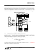
C8051F330/1 devices include a programmable internal high-frequency oscillator, a programmable internal low-fre-
quency oscillator, and an external oscillator drive circuit. The internal high-frequency oscillator can be enabled/dis-
abled and calibrated using the OSCICN and OSCICL registers, as shown in Figure 13.1. The internal low-frequency
oscillator can be enabled/disabled and calibrated using the OSCLCN register, as shown in Figure 13.4. The system
clock can be sourced by the external oscillator circuit or either internal oscillator. Both internal oscillators offer a
selectable post-scaling feature. The internal oscillators’ electrical specifications are given in
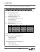
Table 13.1 on page 112.
13.1. Programmable Internal High-Frequency (H-F) Oscillator
All C8051F330/1 devices include a programmable internal high-frequency oscillator that defaults as the system clock
after a system reset. The internal oscillator period can be programmed via the OSCICL register as defined by
Equation 13.1, where f
BASE
is the frequency of the internal oscillator following a reset, ∆T is the change in internal
oscillator period, and ∆OSCICL is a change to the value held in register OSCICL.
On C8051F330/1 devices, OSCICL is factory calibrated to obtain a 24.5 MHz base frequency (f
BASE
). Section 13.1.1
details oscillator programming for C8051F330/1 devices.
Figure 13.1. Oscillator Diagram
OSC
Programmable
Internal Clock
Generator
Input
Circuit
EN
SYSCLK
n
OSCICL OSCICN
IOSCEN
IFRDY
IFCN1
IFCN0
XTAL1
XTAL2
Option 2
VDD
XTAL2
Option 1
10M
Ω
Option 3
XTAL2
Option 4
XTAL2
OSCXCN
XTLVLD
XOSCMD2
XOSCMD1
XOSCMD0
XFCN2
XFCN1
XFCN0
CLKSEL
SEL1
SEL0
OSCLCN
OSCLEN
OSCLRDY
OSCLF3
OSCLF2
OSCLF1
OSCLF0
OSCLD1
OSCLD0
Low Frequency
Oscillator
EN
n
OSCLD
OSCLF
OSCLF OSCLD
Equation 13.1. Typical Change in Internal H-F Oscillator Period with OSCICL
∆T 0.005
1
f
BASE
-------------
∆OSCICL××≅