
Specifications


C8051F330/1
140 Rev. 1.1
15.5.2. Master Receiver Mode
Serial data is received on SDA while the serial clock is output on SCL. The SMBus interface generates the START
condition and transmits the first byte containing the address of the target slave and the data direction bit. In this case
the data direction bit (R/W) will be logic
1 (READ). Serial data is then received from the slave on SDA while the
SMBus outputs the serial clock. The slave transmits one or more bytes of serial data. After each byte is received,
ACKRQ is set to ‘1’ and an interrupt is generated. Software must write the ACK bit (SMB0CN.1) to define the out
-
going acknowledge value (Note: writing a ‘1’ to the ACK bit generates an ACK; writing a ‘0’ generates a NACK).
Software should write a ‘0’ to the ACK bit after the last byte is received, to transmit a NACK. The interface exits
Master Receiver Mode after the STO bit is set and a STOP is generated. Note that the interface will switch to Master
Transmitter Mode if SMB0DAT is written while an active Master Receiver.
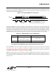
Figure 15.9 shows a typical Master
Receiver sequence. Two received data bytes are shown, though any number of bytes may be received. Notice that the
‘data byte transferred’ interrupts occur before the ACK cycle in this mode.
Figure 15.9. Typical Master Receiver Sequence
Data ByteData Byte A NAS R PSLA
S = START
P = STOP
A = ACK
N = NACK
R = READ
SLA = Slave Address
Received by SMBus
Interface
Transmitted by
SMBus Interface
Interrupt Interrupt InterruptInterrupt