
Specifications


C8051F330/1
Rev. 1.1 193
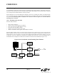
19.2.6. 16-Bit Pulse Width Modulator Mode
A PCA module may also be operated in 16-Bit PWM mode. In this mode, the 16-bit capture/compare module defines
the number of PCA clocks for the low time of the PWM signal. When the PCA counter matches the module contents,
the output on CEXn is asserted high; when the counter overflows, CEXn is asserted low. To output a varying duty
cycle, new value writes should be synchronized with PCA CCFn match interrupts. 16-Bit PWM Mode is enabled by
setting the ECOMn, PWMn, and PWM16n bits in the PCA0CPMn register. For a varying duty cycle, match interrupts
should be enabled (ECCFn = 1 AND MATn = 1) to help synchronize the capture/compare register writes. The duty
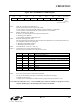
cycle for 16-Bit PWM Mode is given by
Equation 19.3.
Important Note About Capture/Compare Registers: When writing a 16-bit value to the PCA0 Capture/Compare
registers, the low byte should always be written first. Writing to PCA0CPLn clears the ECOMn bit to ‘0’; writing to
PCA0CPHn sets ECOMn to ‘1’.
Using Equation 19.3, the largest duty cycle is 100% (PCA0CPn = 0), and the smallest duty cycle is 0.0015%
(PCA0CPn = 0xFFFF). A 0% duty cycle may be generated by clearing the ECOMn bit to ‘0’.
Equation 19.3. 16-Bit PWM Duty Cycle
DutyCycle
65536 PCA0CPn–()
65536
-----------------------------------------------------=
Figure 19.9. PCA 16-Bit PWM Mode
PCA0CPLnPCA0CPHn
Enable
PCA Timebase
00x0 x
PCA0CPMn
P
W
M
1
6
n
E
C
O
M
n
E
C
C
F
n
T
O
G
n
P
W
M
n
C
A
P
P
n
C
A
P
N
n
M
A
T
n
1
16-bit Comparator
CEXn
Crossbar Port I/O
Overflow
Q
Q
SET
CLR
S
R
match
PCA0H PCA0L
ENB
ENB
0
1
Write to
PCA0CPLn
Write to
PCA0CPHn
Reset