
Specifications


C8051F330/1
Rev. 1.1 195
Note that the 8-bit offset held in PCA0CPH2 is compared to the upper byte of the 16-bit PCA counter. This offset
value is the number of PCA0L overflows before a reset. Up to 256 PCA clocks may pass before the first PCA0L
overflow occurs, depending on the value of the PCA0L when the update is performed. The total offset is then given
(in PCA clocks) by
Equation 19.4, where PCA0L is the value of the PCA0L register at the time of the update.
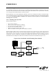
The WDT reset is generated when PCA0L overflows while there is a match between PCA0CPH2 and PCA0H. Soft-
ware may force a WDT reset by writing a ‘1’ to the CCF2 flag (PCA0CN.2) while the WDT is enabled.
19.3.2. Watchdog Timer Usage
To configure the WDT, perform the following tasks:
• Disable the WDT by writing a ‘0’ to the WDTE bit.
• Select the desired PCA clock source (with the CPS2-CPS0 bits).
• Load PCA0CPL2 with the desired WDT update offset value.
• Configure the PCA Idle mode (set CIDL if the WDT should be suspended while the CPU is in Idle mode).
• Enable the WDT by setting the WDTE bit to ‘1’.
The PCA clock source and Idle mode select cannot be changed while the WDT is enabled. The watchdog timer is
enabled by setting the WDTE or WDLCK bits in the PCA0MD register. When WDLCK is set, the WDT cannot be
disabled until the next system reset. If WDLCK is not set, the WDT is disabled by clearing the WDTE bit.
The WDT is enabled following any reset. The PCA0 counter clock defaults to the system clock divided by 12,
PCA0L defaults to 0x00, and PCA0CPL2 defaults to 0x00. Using
Equation 19.4, this results in a WDT timeout inter-
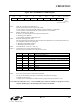
val of 256 system clock cycles. Table 19.3 lists some example timeout intervals for typical system clocks.
Table 19.3. Watchdog Timer Timeout Intervals
†
System Clock (Hz) PCA0CPL2 Timeout Interval (ms)
24,500,000 255 32.1
24,500,000 128 16.2
24,500,000 32 4.1
18,432,000 255 42.7
18,432,000 128 21.5
18,432,000 32 5.5
11,059,200 255 71.1
11,059,200 128 35.8
11,059,200 32 9.2
3,060,000
††
255 257
3,060,000
††
128 129.5
3,060,000
††
32 33.1
32,000 255 24576
32,000 128 12384
32,000 32 3168
†
Assumes SYSCLK / 12 as the PCA clock source, and a PCA0L value of
0x00 at the update time.
††
Internal oscillator reset frequency.
Equation 19.4. Watchdog Timer Offset in PCA Clocks
Offset 256 PCA0CPL4×()256 PCA0L–()+=