
Specifications


C8051F330/1
Rev. 1.1 73
9.2. MEMORY ORGANIZATION
The memory organization of the CIP-51 System Controller is similar to that of a standard 8051. There are two sepa-
rate memory spaces: program memory and data memory. Program and data memory share the same address space but
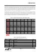
are accessed via different instruction types. The CIP-51 memory organization is shown in
Figure 9.2.
9.2.1. Program Memory
The CIP-51 core has a 64k-byte program memory space. The C8051F330/1 implements 8k bytes of this program
memory space as in-system, re-programmable FLASH memory, organized in a contiguous block from addresses
0x0000 to 0x1DFF. Addresses above 0x1DFF are reserved.
Program memory is normally assumed to be read-only. However, the CIP-51 can write to program memory by setting
the Program Store Write Enable bit (PSCTL.0) and using the MOVX write instruction. This feature provides a mech
-
anism for the CIP-51 to update program code and use the program memory space for non-volatile data storage. Refer
to
Section “11. FLASH Memory” on page 97 for further details.
PROGRAM/DATA MEMORY
(FLASH)
(Direct and Indirect
Addressing)
0x00
0x7F
Upper 128 RAM
(Indirect Addressing
Only)
0x80
0xFF
Special Function
Register's
(Direct Addressing Only)
DATA MEMORY (RAM)
General Purpose
Registers
0x1F
0x20
0x2F
Bit Addressable
Lower 128 RAM
(Direct and Indirect
Addressing)
0x30
INTERNAL DATA ADDRESS SPACE
EXTERNAL DATA ADDRESS SPACE
XRAM - 512 Bytes
(accessable using MOVX
instruction)
0x0000
0x01FF
Same 512 bytes as from
0x0000 to 0x01FF, wrapped
on 512-byte boundaries
0x0200
0xFFFF
8K FLASH
(In-System
Programmable in 512
Byte Sectors)
0x0000
RESERVED
0x1E00
0x1DFF
0x1FFF
Figure 9.2. Memory Map